
|
Last week I explored when volumes of a system or portion of a system become important. Principally, volume in fire sprinkler or standpipe systems becomes important in overall capacity limitations of dry and pre-action systems and in draining portions of wet, dry, and pre-action systems. See the full article here.
This week I've created a basic quick-and-dirty volume calculator based on the length of pipe in a system (don't see the calculator below? View in your browser here): 
Simply select the type of pipe used and enter the approximate length of pipe for each pipe size in the system or portion of a system you're evaluating. I created this when looking at whether I break the 5-gallon volume threshold for portions of wet sprinkler systems, bottom legs of standpipes, or overall dry and pre-action system capacities. Email suggestions or tips for improvement to me at [email protected]. Want to see more like this? Subscribe to these free weekly articles here. It does not necessarily come up often, but the volume of a fire sprinkler system does carry several requirements. Dry and Preaction systems carry water delivery requirements, while all systems carry requirements for drainage. Today I'm summarizing requirements related to when volumes of fire sprinkler systems are important to consider. Dry System Capacity Systems under 500 gallons (1900 L):
Systems between 500 and 750 gallons (1900 - 2850 L):
Systems over 750 gallons (2850 L):
Hazard No. of Remote Sprinklers Initially Open Max. Time of Water Delivery Dwelling Units 1 sprinkler 15 seconds Light 1 sprinkler 60 seconds Ordinary I 2 sprinklers 50 seconds Ordinary II 2 sprinklers 50 seconds Extra I 4 sprinklers 45 seconds Extra II 4 sprinklers 45 seconds High Piled 4 sprinklers 40 seconds Note for Dwelling Units: Dry systems must discharge water in 15 seconds, regardless of system size (NFPA 13 2002 11.2.3.9.1, 2007-2016 7.2.3.1).  Inspector's Tests are used to test water delivery times for dry systems when water delivery time test is required. See this article for details and components on inspector's test and drains. Pre-Action System Capacity Single-Interlock and Non-Interlock Systems:
Double-Interlock Systems of 500 gallons or less (1900 L):
Double-Interlock Systems over 500 gallons (1900 L):
Dry and Pre-Action System Drainage Auxiliary Drain Location:
Trapped Sections less than 5 gallons (20 L):
Trapped Sections more than 5 gallons (20 L):
Wet System Drainage
Trapped sections of pipe less than 5 gallons (20 L): One of the following is required (NFPA 13 2002 8.15.2.5.2.3, 2007-2016 8.16.2.5.2.3.):
Trapped Sections between 5 and 50 gallons (20 - 200 L):
Trapped Sections 50 gallons (200 L) or more:
Subscribe & Share Want more like this? Subscribe to our free weekly articles here. Already subscribed? Send to a friend or share on LinkedIn. How would you design it? That's the topic this week with our first Design Challenge. Here's the project parameters for our theoretical setup: Codes: 2012 International Building and Fire Code Standard: NFPA 13 - 2010 Edition System Type: Wet Pipe System, Fully-Sprinklered Seismic: Occupancy II, Design Category B Construction Type: V-B (combustible) Structure: Solid Engineered Joists Pipe Type: CPVC or Black Steel Surroundings: Unit door runs to the common corridor; additional units reside on each side of these units  If these units connect directly to a common corridor, how would you layout the sprinkler & pipe, and any accessories (hangers, fittings, etc) in this area? Describe how you would approach it below in the comments section or submit your concept to enter the challenge. You'll get points towards the new design leaderboard just for entering, with top-voted designs highlighted on our site. Be sure to submit your concept by the end of this Friday. Voting Next Week We'll take top designs and post them next week for discussion and voting. These challenges could be a great way to think creatively and learn more about the design and review process. Future Challenges Have a scenario you'd like to propose for a future challenge? Send it to us at [email protected]. Want More Like This? If you haven't already, you can subscribe to these posts here, or forward to a friend who might be interested. How do we best learn design, installation and inspection techniques? Repeated exposure to projects, designs, or input from others. In next week's post we'll debut our first Design Challenge, where we'll reveal a small portion of a building with details. Sprinkler designers (of any age and any location) can propose how he or she would design the system for the proposed building. Now, here's where installers, plan reviewers and inspectors come in - We'll then take the top few submissions and post them against each other in the following week for a full-on debate about the pros and cons of each submission. After a vote, the creator of the winning design will be revealed and featured on our site. Step 1: Next Week: Building Area Revealed & Design Submissions Accepted Step 2: Following Week: Design Submissions Posted, Debate Ensues & Votes Tallied Step 3: Winner Revealed  Are you the hotshot designer? Are you the experienced installer? Are you interested in what frustrates plan reviewers or inspectors? Look for our post next week when we reveal the first Design Challenge.
Roughly 160 years ago the development of the industrial revolution brought together people and production into a far greater density than had ever been experienced in history. What was once individual merchants and small productions gave way to the centralized factory. With it came new and larger fire hazards not realized before. Early Manual Systems Early attempts at suppression for fires in these environments (other than manual intervention by responders) included manual piped systems, which fed water to different zones of a building and ended with permeated pipes. These crude systems still required intervention to activate, only provided water after fire had grown, and had issues with plug-holing due to rust or debris in the pipe network.  The next iterations involved coating the pipe with tar that melted in a fire, opening holes in pipe that allowed water to arrive near where it was needed. The delivery of water in the manual system was still delayed, and a remaining issue remained concerning water distribution. Parmelee's Automatic Sprinkler Cue the automatic fire sprinkler, the first modern version of which Henry S. Parmelee famously developed in 1878. The new sprinkler featured a solder-sealed cap between water-filled pipe and a perforated shell, which could more precisely relate to temperature.  Grinnell's Sprinkler The initial sprinkler still delayed in activation as the soldered element was subject to conduction with cool water from the system and a thermal lag from the brass shell. This was improved upon by Frederick Grinnell, who incorporated a soldered element which was not subject to pressures from the water, was exposed to the temperature of the room (removing the thermal lag), and had a a toothed deflector that better distributed water.  Early fire sprinklers often had small deflectors, allowing uprights to direct more spray at ceilings which were often combustible. Over half a century later with manufacturing developments and continued innovation, storage application sprinklers like the Control Mode and then Early Suppression Fast Response were brought to market.  The Impact What interests me about the early development was that we were somewhat destined to end up with fire sprinklers constructed in the way we do now. The fire sprinkler is a reliable mechanical device with far greater precision and reliability than nearly all of the public seems to know. It operates independently, simply, and reliably. Despite so many years between the original sprinklers and now, the principles and basic premises are very nearly what was dreamed about by early innovators. I wonder if in those early years they had any concept of the impact or number of lives those basic devices would save. Get more like this by subscribing to these free weekly articles. Know a colleague might be interested? Send to a friend. We prefer wet-pipe sprinkler systems over dry-pipe systems for a handful of reasons: lower cost, no pipe slope requirements, potentially less points of drainage, can locate inspection & testing at the riser, less maintenance, testing and inspection requirements, no power needs, less noisy, and much less potential for corrosion. However, when dry systems are needed, there's several issues to consider for the end-user. Noise Complaints For owners who are not associated with the intricacies of design and maintenance of dry systems, the most frequent compliant we hear about is with the noise associated with the dry system air compressors. Leaky Systems Dry-pipe systems are fed with pressurized air by a compressor. The compressor run-time frequency and duration is directly attributed to the amount of leakage in the system. Some people directly attribute the leakage of the system to the quality of installation due to the final tightness of fittings. Air injected into a leaky system develops two problems. The first is increased potential for corrosion as fresh air naturally contains water moisture and oxygen, the two ingredients for corrosion. Air that feels comfortable to us offers sufficient products to encourage corrosion, and leaky systems tend to fail with corrosive issues much earlier in their lifetime. The second issue is noise. While it sounds trivial, noise isn't for the employee whose cubicle is next to the riser room. If leaky systems cause issues, why don't contractors prevent or fix leaky systems? Fixing Leaky Systems Once a system is installed and pressure tested to meet minimum standards, finding points of leakage is very tedious and time consuming. Just finding a few leaky fittings requires inspecting every joint and adjusting connection points. Needless to say, if a system isn't installed with tight fittings it becomes a very time-intensive and costly proposition to fix.  Lessening Leakage and Noise in Design As a designer I naturally have less impact on the quality of installation than I do of the design, and there are several ways to help lessen the impact of leakage and noise. Leakage requirements could be mandated to be leak less than prescribed code minimums. I've found this route doesn't exactly make good friends of contractors. Noise can be reduced in a number of ways. First is to use tank-mounted air compressors in lieu of riser-mounted air compressors. Tanks act as a pressurized reserve, where they can reduce the frequency which compressors run in order to supply the system. Mounting to the tank also vibrates the tank, and not the piping network that runs through a building. Vibration on the pipe network requires absorption by the building, which contributes to higher ambient noise. The base of the tank can be isolated with vibration isolation (often rubber pads), again helping to reduce vibration transmission to the building. The downside to tank-mounted compressors is an increased cost and needs for additional floor space.  Another important consideration is where the compressor is located. Often the allotted space for risers are determined architecturally, but upfront coordination and planning to help prevent locating dry riser rooms next to normally occupied spaces can have major benefits. If the dry riser room must be near occupied spaces, consider requesting insulation within walls or acoustic panels to help absorb sound. Quiet-Series Air Compressors Lastly, one of my favorite products to hit the market in the last couple years offers a major solution to the noise issue. I'll start by saying I don't have any family or friends that work for General Air Products. They have not reached out to me to offer any money (although if you're out there General Air I'd be happy to share an address for a check). That disclaimer aside I really love the Q-Series (Quiet Series) General Air Compressors for fire sprinkler systems.  The Q-Series air compressor model can be tank-mounted and is significantly quieter than standard air compressors. The noise for the Q-Series have reduced noise by 20 dBA from the previous 80 dBA of standard oil-less compressors. For drywalled, carpeted rooms the effective sound from the Q-Series compressor is only slightly higher than ambient noise levels of a typical office. The video above (by General Air) shows the difference in compressor noise. Needless to say it would be great for applications in hospitals, schools, offices, hotels, retail, nursing homes, and other areas sensitive to noise. We've found these to be a great solution to a common and intrusive issue of noise with dry risers near occupied spaces. Is this article helpful? Consider subscribing to these weekly articles or sharing it with a colleague who might benefit. You're already familiar with the inspector's test as a required component of a sprinkler system, but today we're diving into the true purpose and details behind this important aspect of a sprinkler system. The purpose of the Inspector's Test can include: providing the ability to (1) test the sprinkler system's alarm/waterflow device, (2) test the opening of a dry-pipe or pre-action valve (for dry-pipe or pre-action systems systems, of course), (3) test the trip time from when the valve is opened to the arrival of water, where necessary, and (4) can aid in venting trapped air. The inspector's test can be coupled as an air vent for a wet system or an auxiliary drain, although we'll explore those components in more detail separately.  Figure 1: Example arrangement of an inspector's test and drain which is remote from the riser Discharge: Used to discharge water during the test or draining of the system. Discharge must:
Drum Drip: Provided for dry or pre-action systems to collect condensate within the system for purging. At a minimum they must be:
Orifice: The orifice (within a sight/site glass) simulates the flow of a single sprinkler in order to ensure that the sprinkler waterflow alarm will activate upon the flow of a single sprinkler. The orifice must:
 Figure 2: Inspector's Test Connection to dry-pipe system when not used as an auxiliary drain Sight/Site Glass: typically provided where water discharge is not visible from the control valve (NFPA 13 2002 A.8.16.4.2, 2007-13 A.8.17.4.2, 2016 A.8.17.4.1). As a side note, I don't understand why Drive Thrus and Site Glasses are spelled the way they are, but I don't try to fight the system. Just know that common language often refers to these as 'site' glasses despite not actually referring to a large area of land. Supply: The supply simply connects the most remote branchline from the riser to the inspector's test (for a remote inspector's test). It must:
Tags must:
Valves:
Wall Penetrations:
 Figure 3: Inspector's Test and Drain Located at a Floor Control Assembly When & Where Required: inspector's tests are required on each wet, dry, or pre-action sprinkler system:
We hope this was helpful. Don't get these? Expand your expertise by receiving these straight to your inbox, for free: Today we're diving into the basic components of a fire sprinkler:  Orifice (Opening)
The orifice varies in size, but has a major impact on the sprinkler's k-factor which ultimately governs the sprinkler's relationship between flow and pressure. Opening sizes vary fairly dramatically but in general are not a major driver for sprinkler selection. Threading The nominal threading sizes range in quarter-inch increments from 1/2-inch to 1-1/4-inch (although some dry pendent shafts do have 1-1/2-inch threads). Thread size of sprinklers can be gathered in the field simply by measuring the diameter of the thread shaft. Sprinklers with a k-factor greater than 5.6 are no longer allowed to have thread sizes of 1/2-inch (NFPA 13 2002-2016 Section 8.3.5). Plug The plug retains the water (and pressure) within the sprinkler and pipe network. Breakage of the liquid-filled glass bulb results in the release of the plug, and thereafter the water. Sealed Liquid-Filled Glass Bulb Modern commercial sprinklers mostly rely on the colored glass bulb as the thermal sensor in the fire sprinkler, but other types are still frequent as well. Color of the liquid within the bulb indicate the listed activation temperature of the sprinkler (and can be found in NFPA 13 2002-2016 Table 6.2.5.1). Frame & Deflector The frame can have many finishes, of which some of the more common are listed above. The deflector offers the basic premise of the fire sprinkler - which is to distribute water in a specific pattern to best combat a fire hazard within an enclosure. Deflectors vary depending upon the style of the sprinkler and work to achieve different objectives. A residential pendent, for example, throws water with greater emphasis to the walls and ceiling where hazards are more commonly present in residential occupancies. Don't receive these articles? Sign up today and get these free weekly posts straight to your inbox. A 3-in-12 pitch to a ceiling or overhang might not appear that dramatic, but I came across a reminder again this past week as to the importance of paying attention to ceiling and overhang slopes. We had a project with a corridor that had a high roof where routing pendents would be impractical. The slope of the corridor was 3 in 12 (3 inches vertical for every 12 inches horizontal), and so we evaluated use of sidewall sprinklers to protect the corridor. Here's where there's three important points to remember came into play that offered a good refresher for us: Sidewall sprinklers are required to have the deflector aligned parallel to ceiling or roof slopes (NFPA 13 2002-2016 Editions Section 8.7.4.2), and, where the slope exceeds 2 in 12 the sprinkler must be located at the high point of the slope and be positioned downward (NFPA 13 2002-2016 Editions Section 8.7.4.2.2). Additionally, as with all slopes, the sprinkler coverage is measured along-the-slope, not in floor area (NFPA 13 2002-2016 Editions Section 8.7.3.1.2).  Those can be easy-to-miss rules and I probably didn't pick up on them for longer than it should have taken when I first started designing fire sprinkler systems.
Other considerations that often pop up in these scenarios include: (1) Use of extended coverage sprinklers may have specific limitations on how dramatic of a slope they can handle, (2) Sidewall sprinklers must be listed for use when they are lower than 6 inches down from the ceiling or roof (NFPA 13 2002-2016 Editions Section 8.7.4.1.1.2). This listing often involves different required pressure and coverage. Reference the product data sheets to be sure installations match their listings. (3) Sidewall sprinklers can't be located more than 6 inches from the wall on which they are mounted (NFPA 13 2002-2016 Editions Section 8.7.4.1.2.2) What issues do you look for with sloped ceilings? Post in the comment section below. Want to see more like this? Subscribe to our Weekly Blog. I have heard several times (often from those outside fire protection) that sprinkler pipe should be located "wherever it can fit around everything else," or something to the effect of "the sprinkler contractor will figure it out." It is under that same mentality that mechanical and electrical engineers will complain when the fire sprinkler contractor is first to installation and they now have to redesign portions of their ductwork or conduit runs. Is it really the sprinkler contractor's fault if no one allocates space for sprinkler pipe in the first place? Coordination often comprises the most difficult and commonly the most overlooked part of building systems design. Ideally, where should sprinkler pipe be located above a ceiling? I've asked a handful of designers, engineers and installers for their take on what the ideal height of sprinkler pipe is to effectively coordinate with other systems while minimizing extra pipe. While each project will vary in detail, much of the consistent thought has been to locate fire sprinkler pipe above the top plane of lay-in lights and underneath ductwork while routing to avoid can lights and slot diffusers (which tend to be deeper than lay-in light fixtures). The lower the sprinkler pipe, the less pipe required to create the drops down to each sprinkler. In my experience (and as others have concurred), locating the pipe centerline 8-inches above the finished ceiling often works well. Under this location it is still important to avoid routing over the centerline of light fixtures, or over diffuers, deep can lights, and slot diffusers. While LED lights have helped keep the depth of lay-in fixtures to less than older fluorescents, it is still important to avoid the centerline of lights as to avoid the fixture hangers. Greater depths or conflicts with any of these elements can of course raise the centerline up to 10 or 12-inches above the finished ceiling.  That being said, the ideal height of sprinkler pipe can be impacted by two other concepts: concealed space protection and seismic bracing. Where concealed spaces need to be protected (such as in combustible construction applications), it may be worthwhile to raise the pipe closer to the underside of the wood structure.
Another important consideration is when seismic bracing is required. Where there is a significant distance between the buildings' structure and the pipe, seismic bracing begins to lengthen and as a result must have greater reinforcement (larger pipe diameters for lower slenderness ratios). In these scenarios, it can be easier to shorten the bracing lengths by raising the system closer to the height of structure. Regardless of where pipe is to be located, establishing space for sprinkler pipe early in a project is a benefit to both upfront engineers and contractors on the back end. What is your routing preference? Have you found any height to be more ideal than others? Feel free to comment if so. If you've found this helpful, please consider forwarding to others who might be interested. Anyone can subscribe to these weekly posts, for free, here. |

ALL-ACCESS
SUBSCRIBEGet Free Articles via Email:
+ Get calculators, tools, resources and articles
+ Get our PDF Flowchart for Canopy & Overhang Requirements instantly 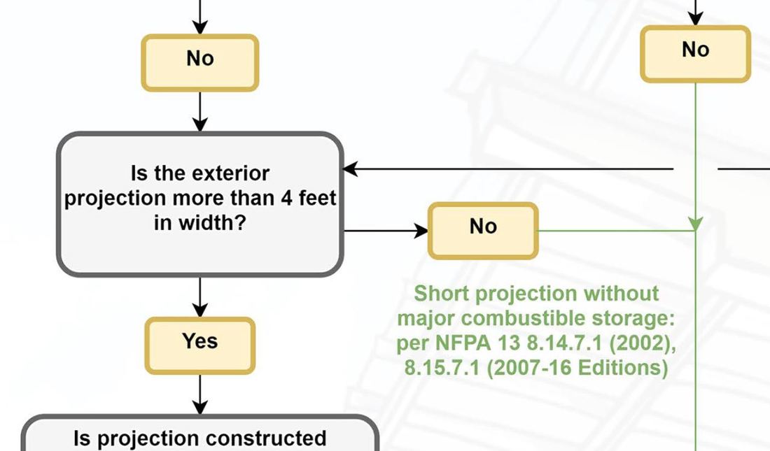
+ No spam
+ Unsubscribe anytime AUTHORJoe Meyer, PE, is a Fire Protection Engineer out of St. Louis, Missouri who writes & develops resources for Fire Protection Professionals. See bio here: About FILTERS
All
ARCHIVES
July 2024
|
 RSS Feed