
|
New Backflow Preventer Database I've started a new database for backflow preventers in a similar way to the popular fire sprinkler database. Backflow preventers are and have been a mainstay on fire sprinkler systems to protect the public water supply from backsiphonage. They're required by both the International Plumbing Code (608.16.4) and the Uniform Plumbing Code, two popular enforced codes in the US and elsewhere.  The new Backflow Preventer Database is in beta and available to current Sprinkler Database subscribers. Backflow preventers have a number of different parameters. There's differences in types (double check, double check detector, reduced pressure zone, and reduced pressure detector), materials, listed rating, sizes, connections (flanged, grooved), valve types (outside screw and yolk or OS&Y, non-rising stem or NRS, butterfly valves, or ball valves), orientations (horizontal, vertical, n-pattern, y-pattern, z-pattern), and various certifying agencies (UL, FM, ASSE, CSA, NSF, USC). Most of my curiosity and the reason for building to the tool was (1) to determine what is actually available on the market today, (2) what are the differences between types and models, and (3) how can I easily access manufacturer websites, product data, CAD details, and Revit families with one-click. That curiosity led to the new Backflow Database. While it's still in an early beta-testing mode users who are already subscribed to the Sprinkler Database can now access the Backflow Database by logging in. If you're a Sprinkler Database user, give it a try and let me know what improvements I can make. Right now the database includes Wilkins, Ames, and Febco models. Have a manufacturer you'd like to see? Have ideas for updates? Email me at [email protected] or comment here. Thanks in advance! Vote on New Tools & See What Else is Coming Soon Around here we're always in development on new and improved tools to help designers, reviewers, inspectors, installers, and engineers in the fire protection industry. You can now see, and vote, on upcoming tools that are in development for MeyerFire.com. The "Coming Soon" page is now live under "Tools" on the website header. Take a look at upcoming tools, rate each, and share ideas that we can work towards on this new area of the website. Get Articles & New Tools Weekly
Don't get these articles emailed to you for free? Subscribe today & get our Sprinkler Canopy & Overhang Guide.
Quick updates for this week - thanks to helpful recent suggestions I've updated the Friction Loss Calculator to include several NFPA 13-provided fittings as well as fluid velocity among various sizes.
With a flow rate and length of pipe, you'll see fluid velocity as it's own column in feet/second. While both NFPA 13 and FM Global do not have any limitations on fluid velocity, it's a good point of reference to reference how quickly a fluid is moving through the pipe. The brief list of fittings at the bottom allow you to compare friction loss across a number of different assembly sizes, so you can compare runs of pipe or assemblies at various sizes all at the same time. Can't see the tool above? See it here: If you don't already get updates on our latest tools and weekly articles, you can get them for free here: One of the popular aspects of fire sprinkler installations that is overwhelmingly familiar to fitters in the field yet something I hardly understood back as a new graduate is pipe connections. Today I'm breaking out some of the popular methods of joining steel pipe in fire sprinkler systems. Steel Pipe While copper, CPVC and PEX are listed for use in fire sprinkler systems (PEX is only for NFPA 13D systems), black steel pipe remains the most popular pipe material for commercial fire sprinkler applications, at least within the United States. For steel pipe, the primary means of connecting the pipe include threaded fittings, grooved fittings, plain-end compression fittings, flanged connections, and welding. Plain End Pipe Steel pipe when initially formed has flat cut, unpolished ends. This is generally referred to as plain end pipe. Plain end pipe can be connected by compression fittings or push-on fittings, which bite into the pipe to prevent separation. While popular for other building systems, use of plain end pipe and compression or push-on fittings are not used in sprinkler systems due to the relatively high pressures sprinkler systems experience.  Threaded Pipe Perhaps the most common current method of joining fire sprinkler pipe for smaller pipe diameters, threaded pipe makes use of helical crests that screw into a female threaded fitting. To create threaded pipe, a plain-end pipe is cut with a threaded machine decreasing the thickness of the pipe wall. As a result, the areas remaining below and adjacent to the thread become weaker and more susceptible to corrosion breakthroughs with the thinner wall of pipe.  As compared to grooving or welding pipe, the pipe wall thickness must be thicker to accommodate the cut-in threads (ASME B1.20.1) for threaded pipe. NFPA 13 6.5.1.2 (2002-2016 Editions) addresses minimum pipe thicknesses for threaded pipe up to 300 psi, unless the pipe is separately listed for fire sprinkler use:
When connecting threaded pipe, joint compound or pipe tape is applied to the male thread to avoid water leakage. While threading larger pipe was common throughout the early to mid twentieth century, the weight of Schedule 40 pipe and difficulty of turning large diameter threaded pipe makes threading an uncommon choice for larger diameter sprinkler pipe today. Grooved Pipe Grooved pipe is a popular method of pipe joining invented by Victaulic with roots in both World Wars to deliver water and petroleum with faster, more reliable method of pipe connection.  Grooved pipe is formed by either cutting into the pipe (cut groove) or by pressing an indentation into the pipe (roll groove). Cut groove pipe results in a lesser pipe thickness, weakening the pipe and also offering less protection against corrosion. Roll grooving, while keeping the pipe wall thickness, also poses issues in low-sloped dry and pre-action systems as the rolls on the interior side of the pipe create areas to trap water and create an air-water interface for corrosion to occur.  Grooved pipe has a number of inherent advantages. Smaller pipe thicknesses are permitted for grooved pipe, resulting in thinner pipe which makes transporting, carrying, and lifting into place easier. Minimum thicknesses for Grooved Pipe:
With thinner, lighter pipe and easy grooved coupling options, labor can be less difficult and significantly quicker. Welded & Flanged Pipe A less common but additional option for restraining pipe is welding. Pipe can be welded as an outlet - where a welding equipment cuts a hole in one pipe whereafter another pipe segment is held in place and the two are welded together.  Welding has a few advantages - it can be (and often is) performed in a fabrication shop, does not require any additional fittings, and can allow for more custom pipe arrangements. For instance: a 4-inch x 4-inch x 1/2-inch outlet for a pressure gauge connection might be a special order reducing tee (ie: costly); as a welded outlet, it could be quickly and easily welded into place with the outlet easily threaded or grooved. Welding is not limited to outlets, however. "Slip-on flanges" can be welded to the hub side of the flange to a piece of pipe, allowing two flanged fittings to be bolted together with a gasket in-between.  Flanged pipe and fittings are common around fire pump assemblies, as NFPA 20 annex material even notes that "flanges welded to pipe are preferred" despite screwed, flanged mechanical joints or other approved fittings are allowable (NFPA 20 2003-2007 5.13.2.1, 2010-2013 4.13.2, 2016 4.14.2, 2019 4.15.2).
Different installing contractors often have different preferences on fabricating pipe. Personally I've worked with some who prefer to have welded outlets along 21-foot lengths of pipe and groove as much as allowed for a job to use lighter, thinner pipe, including through branch piping. Others prefer some flexibility of threaded pipe to make quick changes in the field and provide a more traditional, tightly-connected threaded system. What do you commonly see? Does your team have preferences for fabrication methods? Discuss this here. Follow the Movement Get these articles, for free, once a week. Follow the movement for better fire protection here.
One fundamental aspect of fluid movement is thrust force, which is created when a flow path bends, tees, wyes, dead ends, or reduces. In order to counter the unbalanced forces that are created at these locations, the pipe and fittings must be mechanically restrained from separating, welded together, or otherwise fixed from movement.
Push-On Underground Joints One popular method of preventing pipe separation for underground pipe is gasketed push-on joints for underground pipe that do not have special locking devices, but permit pipe to be installed in any direction and at any point along the path. Role of Thrust Blocks In order to prevent the internal pressure from forcing the pipe and fittings to separate, blocking (or "thrust blocks") provide stability and allow the surrounding soil to accept the thrust force from the pipe assembly. Soil conditions vary in its ability to handle forces. Thrust blocks allow a narrow point force to be spread and distributed across larger areas of soil down to a pressure that the soil can bear. 
Thrust blocks take the point force created from the change in direction of the water (static and dynamic)
and distribute that force to the soil. The Calculator The tool below is an early part of a larger effort to determine the thrust block detailing. In the coming weeks, I would like to add block height, width, volume and visualizations to detail the parameters. Don't see the tool below? Click here. For those who work routinely with thrust block and their calculations under NFPA 13, what else could I add to this tool to be more useful? Comment here or email me at [email protected] if you have any ideas. The Toolkit - Launches Next Week The long-awaited Toolkit launches next week - complete with this and other tools in a downloadable software package. Be the office hero with quick and printable tools, as well as access to the Sprinkler Database and the ability to post questions to users on the Daily Discussion forum. Look out for news regarding the launch next week. Get More Like This If you don't already subscribe to these articles & resources, you can do so, for free, here: Based on the feedback and response about an earlier article about Sprinkler Requirements in Bathrooms, it only makes sense to extend a roadmap for navigating requirements concerning sprinklers in closets. For such a simple topic, this work took two weeks and will still require further exploration in the coming weeks. Basic Concept The premise for determining whether a closet requires a sprinkler would intuitively be fairly easy, as the question implies a yes/no black and white answer. The development to get to where we are currently, however, is governed by experience and studies into the risk/benefit posed by providing sprinklers in closets. Does providing a sprinkler within a closet improve building protection and aid in better life safety? Yes, in most (or perhaps even every) circumstance.  While in concept determining whether a sprinkler is required for a closet would typically be a straight-forward cut-and-dry process, the code path to determine whether it is required or not is dependent upon multiple factors. Competing Objectives However, there are also competing objectives for standards such as NFPA 13R (Low-Rise Residential Occupancies) and NFPA 13D (One- and Two-Family Dwellings and Manufactured Homes), which is to create affordable systems with a life-safety objective in lieu of property protection. Attempting to create affordable systems is not inherently a bad thing; it only creates less friction between the building owner paying for or deciding to install a sprinkler system. Why Not All Small Closets? Why is a 10 sqft apartment closet any different than a 10 sqft closet in a motel? They could be constructed the exact same. The difference is in the totality of the situation: NFPA 101 and by extension NFPA 13 recognize that "inherent ignition sources and combustible fuel load" are very different for different occupancies. In general, where closets can more easily accumulate high fuel loads (longer-term living situations), the less likely a sprinkler will be allowed to be omitted. NFPA 101 - what about the IBC? NFPA 101 outlines specific allowances based upon occupancies to determine closet sprinkler requirements. The International Building Code does not address these same areas, rather deferring those requirements to NFPA 13, 13R, or 13D. What if both IBC and NFPA 101 Apply? Many healthcare applications find that the IBC is enforced by a local jurisdiction while NFPA 101 applies due to healthcare credential requirements of CMS (Centers for Medicare & Medicaid Services). Typically the most stringent requirement would be the guiding direction in these instances, but it would be prudent to work with code authorities to resolve these conflicts where they arise. 2016 Edition Changes The 2016 Edition of NFPA 101 offered a handful of changes specific to closets. You'll see in the breakout below that this flowchart only applies to the 2016 Editions of NFPA 13, NFPA 13R, NFPA 13D, and NFPA 101. With so many changes between the editions, I'm planning to recreate this chart with prior editions for reference. The Flowchart The chart below is a visual summary of the decisions that lead to various sections of code. Despite the simple yes/no nature of whether a sprinkler is required in a closet or not, you'll notice the complexity of the decision tree within NFPA 101. Click on the chart for an enlarged version below.  Flowchart for 2016 closet fire sprinkler requirements Don't get these articles already? They're free - subscribe here.
After posting the N^1.85 Water Supply Graph a couple weeks ago, I was asked about creating an SI (International System of Units) version of the same graph for "those living on that side of the world."
I looked it up, and it turns out "that side of the world" is literally everyone except Liberia, Burma, and the United States. So for those across the pond or literally right next to us that don't use the ol' foot-candles system of measurement, here's the N^1.85 Fire Suppression Supply Graph in metric. Please give it a try and let me know your thoughts in the comments below. If you're relatively new to MeyerFire - welcome! This site and the tools here are created to help you create exceptional fire protection. I've worked in large companies with over 45 people dedicated fire protection staff and I've worked as a solo practitioner, and what I've found is that regardless of the work environment there is a big need for regular tools that can improve our workflow: tools with better analytics, tools to speed workflow, and tools that allow us to make better decisions. This site and the tools here are created for one purpose: to help you do exceptional work. They're created for the freelancer, the plan reviewer, the designer lost in the cubicle farm, the woman interrupted in meetings, the rookie, the mechanical who dabbles in fire protection, the intern, the ravenous learner, and the senior. Fire protection is too important to not do well. Here's a summary of tools available to date, with brief descriptions.
If you haven't already subscribed or shared this with someone who might be interested, please do. There are big plans for the website with new tools and resources that are already in development. Thanks for being a part of the story.
A few weeks ago I received a call from a sprinkler contractor who needed to provide a water supply graph for a flow test he conducted.
I had a canned sheet I had developed for my own flow tests, but it was a basic graph that showed a curve and didn't match the traditional N^1.85 hydraulic graphs common for water supply curves. Since then I've tinkered and come up with an accurate chart that takes flow test input values, calculates total flow and draws the curve along the N^1.85 chart. 
The N^1.85 chart is particularly useful for fire suppression systems because the Hazen-Williams formula is based on the relationship that pressure relates to flow to the 1.85th power. 
When the x-axis, or the hydraulic flow is then scaled to the 1.85th power, hydraulic curves become straight lines which becomes easier to graph and compare. Prior to everyone carrying a computer in their pocket, these graphs were likely much easier to use for summaries and comparisons. The water supply information is what is provided as part of a two-hydrant flow test. The design input information would be the system demand side and can be used for quick comparisons. Personally, I only use this setup for flow test reports and water supply comparisons. Fire sprinkler hydraulic calculation software takes care of the graphs and outputs I need after I've completed the hydraulic calculations.
On a side note, I've had several people ask about getting access to all of the tools I've created to use on their own computer with the ability to produce printable output for record keeping. Thanks again to those who asked - these are available now as part of the MeyerFire Toolkit - a collection of all of our quick-hitting tools. The Toolkit is also included as part of MeyerFire University at no additional cost.
Don't get these free weekly articles? Subscribe here. My goal with creating this website and tools is to support those who want to create great fire protection. It's almost here! The MeyerFire Sprinkler Database goes live tomorrow at 9am Central. Check out more detail about our long-awaited project with our video: Can't see the video? View it here. See all the details at www.meyerfire.com/sprinkler.
Updated November 2020 I get this question all the time from architects - especially when working around apartment, hotel, senior and assisted living facilities. "Are sprinklers required in the bathrooms?" I don't mind the question at all, because it has a relatively straightforward answer - they're either allowed to be omitted or not. The path to determine whether an exemption applies is actually fairly complex which I'll explore today. Note that this article covers requirements but also some helpful explanatory material pulled in from non-enforceable parts of codes and standards (such as the annex material). Side Note: Big Launch Coming This is week 2 of my 3 part series in creating resources for sprinkler designers, engineers, inspector's, and contractors. Stay tuned for the big product launch coming in the next few weeks. Now back to the article - Why Allow the Omission of Sprinklers in Small Bathrooms? Typically, since bathrooms require regular cleaning and are subject to variable humidity, surfaces can often be ceramic or non-porous. These easily washable surfaces tend to also be less combustible than other building materials. In studies of apartment fires where sprinklers were present, for instance, bathrooms were the area of fire origin in only 1% of total fires and resulted in no civilian deaths, civilian injuries or property loss (NFPA 101 Annex Material in A.30.3.5.4 & A.31.3.5.4). From a risk perspective, small bathrooms present a relatively low risk for fire origin and growth as compared to other areas of a building. Also, bathrooms in buildings with dwelling units also can comprise a major potential additional cost when they are repeated within each unit. Omitting sprinklers can offer a huge cost savings to these type projects.  For some residential occupancies, there can be significant cost savings to omitting sprinklers in small bathrooms throughout a building. Due to relatively lower risk of ignition, building codes and standards permit omissions for specific applications. Building Codes Overrule NFPA 13 Starting with the 1997 edition of NFPA 101, language was introduced into the code to override the requirements in NFPA 13 and NFPA 13R. NFPA 101 only overrides NFPA 13 for specific occupancies, which are outlined below. The International Building Code also introduced provisions for omitting sprinklers in restrooms, beginning with the 2015 International Building Code. These sections are also reflected in the companion International Fire Codes. If Small Bathrooms Omit Sprinklers, Is the Building Still Fully Sprinklered? Yes; where NFPA 13 omits sprinklers the building is still sprinklered in accordance with NFPA 13 and is typically considered fully sprinklered. Where omissions are allowed by NFPA 101, the building is also still typically considered to be protected throughout (reference NFPA 101-2015 A.11.8.2.1 or NFPA 101-2018 A.11.8.3.1, for instance). Are Bathtub or Shower Enclosures included in the 55 sqft limitation? Yes; they are typically considered part of the room as NFPA 13R-2002 introductory material clarifies. If There’s Just a Toilet, is it Still a Bathroom? Yes; annex material of NFPA 13 (2002 A.3.3.3, 2007-2018 A.3.3.2) clarifies that a toilet rooms is still considered a bathroom. Also, two adjacent bathrooms are still considered separate rooms provided that they’re enclosed with the required level of construction. If There’s No Door, is it a Bathroom? Weird. This must be some kind of a HGTV renovation for hippy-people if you don’t have a door for some bathroom privacy. Oh and yes, a door is not required in order to omit sprinklers as long as the bathroom complies with the definition of a compartment (NFPA 13 2010-2016 A.8.15.8.1.1). The Quick-Guide to Determine Permitted Bathroom Sprinkler Omissions:  Get Access
MeyerFire.com is all about creating helpful articles, tools, and calculators for fire protection designers, engineers, review authorities, inspectors, and contractors. Don't receive these weekly resources already? Get them free here.
Last Week's Survey Results
Last week I sent a survey asking for "challenges associated with sprinkler identification and design selection." I really appreciate the input provided, there was really helpful and great feedback: common challenges people noted in the survey included sprinkler market availability, listing and approvals, field identification, adherence with product data, price, storage limitations, pressure requirements, and spacing requirements. Anticipation for the Big Launch I am very excited to say that I've been developing a live resource over the past couple years to address almost exactly those challenges. Stay tuned, as more details will be available about the launch in a few weeks. In the meantime, I'm also excited that the blog posts over next three weeks (starting with today) will feature tools designed to help streamline and speed workflow for inspectors, designers and engineers. Part I of III: The Cloud Ceiling Calculator This first week covers the relatively new allowances for cloud ceilings. 
"Cloud" Ceilings where directly addressed in NFPA 13 beginning with the 2016 Edition
Cloud Ceilings include any ceiling installed in the same plane with horizontal openings to the structure above on all sides (NFPA 13-2016 3.3.5.1). The "cloud" is simply in reference to the appearance that the ceiling "floats". The new provisions in NFPA 13-2016 allows sprinklers to be omitted above cloud ceilings where the gap between clouds (or clouds and walls) meets a maximum allowable dimension based on the floor-to-cloud ceiling height. Backed by Research What I love about this new verbiage is not just that the NFPA 13 committee addressed a specific topic that many had asked about for some time, but that the development of the rules for this section are based on a commissioned project by the Fire Protection Research Foundation. So what is the guidance based on the research findings? Spaces above cloud ceilings do not require sprinklers where the openings have a combined total area of not more than 20 percent of the ceiling, construction feature, or plane used to determine the boundaries of the concealed space and the cloud ceiling arrangement meets Section 8.15.24.1 (NFPA 13-2016 8.15.1.2.1.3). Limitations I've already mentioned that the opening between all cloud ceilings can't be more than 20% of the total room area, but there's a few others that also apply:
Ceiling Spacing Calculator If these limitations can be met, sprinklers may be omitted above where the spacing below the ceiling complies with Table 8.15.24.1. The table addresses the maximum protection area based upon the research, and is a little less than intuitive. Here's a quick calculator that takes your parameters and gathers the appropriate maximum sprinkler protection area (click the link to see the full tool, with a schematic section of the ceiling arrangement): Enter your project parameters in the red highlighted cells to test your situation. Give it tool a try and let us know what you think in the comments section below. If you've found this interesting or helpful, consider getting more of these tools by joining our email group. Already subscribed? Share this on LinkedIn for others who might find it interesting. |

ALL-ACCESS
SUBSCRIBEGet Free Articles via Email:
+ Get calculators, tools, resources and articles
+ Get our PDF Flowchart for Canopy & Overhang Requirements instantly 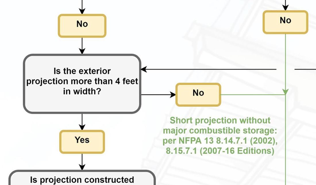
+ No spam
+ Unsubscribe anytime AUTHORJoe Meyer, PE, is a Fire Protection Engineer out of St. Louis, Missouri who writes & develops resources for Fire Protection Professionals. See bio here: About FILTERS
All
ARCHIVES
July 2024
|


 RSS Feed