
|
How do we solve the systematic problem we have with fire protection bid documents? Some, if not much of the plans and specifications that go out for bid are generally helpful. A quality set of fire protection bid documents:
These types of bid sets do happen. But far, far too often, they don’t. It’s systematic, and makes every step of the design and installation process far more difficult and far more costly than it could be. NOT FAULTLESS I don’t even want to pretend I’m not at fault here. I’ve designed poor projects. I’ve slacked on coordination, and detailing. I’ve glossed over parts of a project that I shouldn’t have glossed over. It’s been painful. But this is something that we can change. WHAT CONTRACTORS SAY For some years now I’ve spoken with sprinkler contractors, architects, and consultants about this. If you’re a contractor, especially if you work in estimating - you could provide countless examples of terrible bid documents. Bid documents that actually get in the way of you doing code-compliant, efficient work. You could speak to this far better than I can. In these conversations, over and over, I’ve heard one key feature that I think many consultants in the MEP space miss. It is far better to have no fire protection bid documents, than to have bad fire protection bid documents. NO FIRE PROTECTION BID DOCUMENTS? That’s important, and counterintuitive. It is far easier for a sprinkler contractor to look at a project and define their own scope, and put a price to it, than it is to try and bid a set of documents that:
If that sounds too far, ask your closest estimator friend. They see this all the time. How many projects do we see underground feeds piped 20-ft before rising up? How many times do we see Star, Central, or Gem still specified today, in 2024? How many times do we see projects wanting a fixed-price bid yet have zero information about the water supply? How are those documents helpful to a bidder? They’re not. MY ANALOGY The analogy that I’ve had in my head and finally am able to bring to life a little is the road, showing the different tiers of fire protection bid documents: 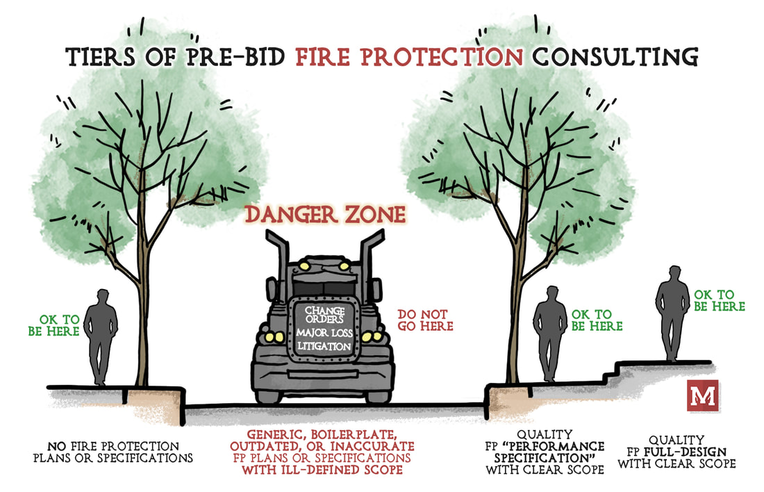 1 - NO FIRE PROTECTION BID DOCUMENTS
There’s the sidewalk on the left, where we have no fire protection bid documents. Let’s say we have a single-family home with an NFPA 13D system. Scope is simple, perhaps we have no specific owner needs, and it’s unambiguous. That type of project probably warrants no upfront, pre-bid fire protection involvement. It wouldn’t have to just be a single-family home though. What about an add & relocate job for a small retail space. Or a small office building. Those can, and often do, work just fine without any upfront fire protection bid documentation. Design-build all the way. 2 - QUALITY "PERFORMANCE SPECIFICATIONS" Then we skip ahead to quality “performance specification” documents. These do all the things we’ve talked about. They don’t necessarily show pipe or sprinklers, but they clearly define the scope, they communicate clearly, they answer major scope questions, they address and alleviate major issues or coordination challenges upfront, and they make it easy to put a price to the job. That’s a quality set of “performance specifications”. 3 - QUALITY "FULL-DESIGN" For high-end jobs, or high-hazard jobs, or critical function or high-visibility or unique jobs – perhaps we’re looking at a full-upfront design prior to bid. Full-design isn’t free, nor quick, and isn’t necessarily the answer for every job. But, as we’ve talked on this topic before; if it’s done well, and thoroughly, then fully-detailed plans can be a tremendous asset to a project. They can eliminate ambiguity and really dial-in exactly what work needs to be done. AND... THE DANGER ZONE What about the DANGER ZONE? There’s a gap, and it’s in-between no bid documents and quality “performance specifications”. And that is the Danger Zone. This is the lane of bad bid documents. These are all the bad things. Inconsistent, boilerplate, confusing, inaccurate, unachievable, irrelevant, or not actually code-compliant. What happens when we live in that lane? We get hit by the proverbial bus. Change orders. Litigation. Or much worse – a fire happens with major loss. This is not the spot to be. WHY DO WE STAY IN THE DANGER ZONE? I’m fairly confident that those who live in that space don’t want to be there either. They feel compelled because the client asks for fire to be included. They feel pressure because competitors are offering to do fire protection. They feel they can’t spend enough time on fire because there is hardly any fee there. Honestly – these are all poor excuses. If there isn’t enough money in the job to put together a quality set of fire protection bid documents – then don’t do them at all. It is far better to have no fire protection bid documents, than to have bad fire protection bid documents. HALF-BAKED DOESN'T HELP Bad, sloppy, half-baked documents don’t help. They don’t solve anything. They get in the way. If you’re the MEP who finds yourself in this area, having that conversation with an owner or architect and there’s just not enough fee to do quality work – then just exclude it entirely. If an architect insists that it get thrown in or done on a microscopic budget, then just ask them to hire a fire protection consultant separately. Half-baking a set of documents is not worth the hassle or the liability. It also doesn’t actually help. When you do take it on, do it well. We all benefit from that. YOUR TAKE If you’re a sprinkler contractor or architect – I really want to hear from you. Where do you land on this? When projects have gone south or had major change orders – what happened? Would being in a different tier have changed the result? Comment below, would love to hear your take. And, thanks, as always, for reading and being a part of the community here. We will get this right. The majority of bid documents for fire sprinkler work is some form of delegated design. A consulting engineer frequently does not provide all of the detail about a system (pipe locations, size, hanging methods, hydraulic calculations, etc). Why is that? In other disciplines, the opposite is common. Mechanical Engineers regularly selects a system type and lays out ductwork in a one-line or two-line configuration on a plan before a contractor bids the system. Electrical Engineers commonly size up, calculate and provide power and lighting locations on plan with an overall one-line diagram. Even plumbing often has plans for domestic water feeds and sanitary waste. Why doesn’t that happen for fire protection? First, the biggest disclaimer today, I’m not advocating for all design to be upfront. Or even a majority of it. I do see many applications where a quality FPE consultant can provide a tremendous amount of value to a project. I explored this a bit with The Delegated Design Problem and in A Practical Design Spec Checklist. But I would like to start the conversation and get your ideas on why we are where we are today with why designs are not done upfront. Here is why I think all sprinkler design is not completed upfront, before bid time.  #1 WE DON’T WANT EVERYTHING UPFRONT
Overwhelmingly, the sentiment I hear from sprinkler contractors about ‘full-design’ fire sprinkler drawings is that they wouldn’t want upfront designs for all projects. Why? Because in some (or many) cases, sprinkler contractors feel that upfront design either limits their flexibility or is of very poor quality, or both. A design that doesn’t coordinate with other systems, or ‘leaves coordination’ for the sprinkler contractor, is problematic. It’s difficult to bid and difficult to work with after a project has been awarded. How much needs to be ‘coordinated later’? How ‘real’ is the design? Is it less efficient than the contractor could have laid it out? Many who have designed on the contracting side feel that real-world “fit” and doing the sprinkler layout are one in the same. You can’t ‘rough-in’ a layout without thinking about conflicts and making it actually work in the real world. As an extreme example, I think most could agree that a basic NFPA 13D layout does not need upfront involvement by a consultant. Could they help? Perhaps. Could they provide value? Perhaps. But it does not need a high level of involvement. Now there’s a big counterpoint to this. Just because we don’t want upfront design on all projects doesn’t mean it wouldn’t be beneficial on some projects. Projects that have very specific needs, unique needs, high-visibility challenges, coordination challenges, or that require a specialized set of expertise could very much benefit from upfront involvement. Maybe it’s a retrofit in a high profile historic museum. Maybe it’s suppression for an automated storage retrieval system. Maybe it’s a unique storage configuration that is outside the bounds of NFPA 13. In these types of situations, involvement from a quality FPE consultant can address code concerns and clearly define the scope. It can help mitigate a lot of risk for contractors by doing so and help everyone bid apples-to-apples instead of a wide-open, ill-defined scope. #2 INADEQUATE WORKFORCE (INDIVIDUALS AND COMPANIES) Perhaps the alternative reason is the lack of expertise in the workforce. We simply don’t have enough people, nor expertise, to take on every project. Even if we wanted upfront involvement to a high-level of detail, we as an industry couldn’t pull it off. We don’t have enough bodies, nor enough qualified expertise. Is it an issue? Absolutely. Does the lack of people affect how well we advocate for fire protection itself? Absolutely. Could the construction experience for architects and owners and contractors actually benefit from more and better individuals working upfront on project? Absolutely. But until we catch up on the quantity of our own workforce, we simply can’t take on more involved work. #3 LOCATION OF THE EXPERTISE Another reason we don’t perform highly-detailed layout work upfront is the location of where expertise for layout technicians often falls – and that’s in contracting. Anecdotally I know far more layout technicians in contracting than I do in consulting. In our survey of nearly 500 industry professionals in 2022, of those who had roles as a designer or layout technician, 68% of them worked for contractors (another 4% were self-employed). That’s different than other disciplines where there is plenty of design and layout expertise embedded in consulting. #4 DOWNSIDES: COST, INFLEXIBILITY, & SCHEDULE Involving expertise upfront isn’t free. There’s a cost associated with it. We mentioned it before and stipulating a full layout upfront also set some parameters in place that can limit the creativity and efficiency of a contractor-provided layout. Lastly, there’s time needed to do that work upfront. Having a high-degree of involvement may not be a positive impact to overall project schedule. SO CAN WE KILL-OFF UPFRONT INVOLVEMENT? It sure feels like I’ve put out a hit piece on any upfront involvement in fire sprinkler design. The question is – does all design need to be done upfront? By an engineer or consultant, or someone other than a contractor? That answer is no. All design doesn’t need to be upfront. We couldn’t pull it off anyways, but it could also be costly and obstructive for many small or simple project applications. Is there value to having upfront involvement? Absolutely - when it’s done well. Consultants provide tremendous value, all-around, when:
Do consultants need to be doing fully-detailed layouts to accomplish this? Often no, though sometimes it could help. HOW DO WE RESHAPE THE WORK? In an SFPE Magazine Article in 2022, Thomas Gardner wrote “There is a happy medium between no delegation and full delegation of the fire protection system.” Count me in that camp. Many times when the subject of “Delegated Design” gets brought up, we instantly jump to extremes. Either all design should be by the EOR, or no design should ever be by the EOR. On one hand we have many military projects that specify the Qualified Fire Protection Engineer (QFPE) to be in direct charge of the layout upfront, if they don’t perform it themselves. On the other hand, we have an ever-growing amount of residential projects in North America that have no FPE or consulting involvement whatsoever. Both of these situations are not necessarily at odds. We can strike the balance between the two, and we can do “Delegated Design” better than what’s being done today. We can improve the quality of upfront documentation that defines scope and goes out for bid, and at the same time, still provide flexibility for the contractor and an overall lean project delivery. Part of solving that puzzle is looking realistically about what different approaches mean – how they look – seeing good and bad examples – and moving forward to introduce, educate and advocate on what better “Delegated Design” means in the future. For literally the past two decades there has been growing momentum to bring light to the issue. We’re not far from having more resources to define what “better” looks like and how we can easily get there. WHAT'S YOUR TAKE? We had a great dialogue about the problem of Delegated Design before, that's here. But what's your take on why work isn't provided upfront? Is it just tradition? Just the way things always have been? Is it any of the reasons I've cited? Why is our delivery method so different from Mechanical, Electrical, Plumbing or Structural? What separates us from other disciplines? Comment below - would be happy to hear your take. We tried out something new a couple months ago with a Detail Pick-Apart covering a dry sidewall sprinkler at a deck. We had a great response - healthy discussion from a wide variety of perspectives. Way back when we even talked about different parts and purposes for components of a wet riser. It's the dialogue that I often find the most helpful in seeing and understanding perspective that I simply just don't have. No detail is perfect, nor is it applicable in all situations. No way. It's one possible solution to some situations. That said, it can be really helpful to have open discord and learn from it. Quick rehash on ideas for critique and discord: USE CASES: What are good use cases for this? PROS: What benefits does an approach like this bring? CONS: What are the negatives with an approach like this? IMPROVE: What ways can this approach be improved?  What critique would you offer here?
Thanks, as always, for being part of making the industry better. You’re on a jobsite. On the phone with the boss back at the office. You’re looking up at a portion of the sprinkler system and have a question about that one piece of pipe. How do you describe that piece of pipe? What’s it called? It sounds silly, but up until Monday I’m not so sure that I knew the proper name for each segment within a sprinkler system. Like the true, proper terms that I should have learned way back when. There are a few things that can impact that – one is informal regional terms, which can cause some inconsistency. One is that up until Monday I’d never actually read all the definitions in NFPA 13 for each stick of pipe. One is that when I’d get cross-eyed looks when talking about a specific piece, I’d usually just point to it in conversation and move on. Well – as we do around here – it’s time to bring this topic out into the light and maybe we can all learn a bit from the discussion. Here’s a basic diagram of a sprinkler system, which each pipe path identified as best I understand it today: 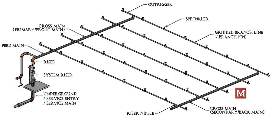 Is this consistent with the terms you use? What other names (maybe keep it PC?) or terms do you use? If not, what terms (even informal ones) do you use to describe each pipe? 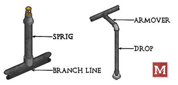 Take a look at the diagram above and some of these pictures and let us know here.
USE GOOGLE FOR FLOW TESTS & SITE PLANS I sometimes (maybe often) have to learn things the hard way. This tip today comes from the “Lessons Learned” file, where it took me two bashings over the head before I had my ‘aha’ moment. Forgive me if this is obvious and you've been doing this for years. Again, I have to learn things the hard way sometimes. So what is it? What are we talking about? Clearly identifying the location of the water supply. And the ‘aha’ answer – well it’s really simple and can be really helpful. On many projects we use a flow test to get an idea of the available water supply. We use the available water supply curve to calculate how much pressure and how much flow we have available that can serve our suppression system (sprinkler, standpipe, etc). Flow tests carry a whole lot of engineering nuance. A flow test is simply an instantaneous “point in time”. It doesn’t account for demand variations like the time of day, day of the week, or seasonal demand like the lawn irrigation system next door. We’ll save that conversation for another day. One other key factor that a flow test carries is that it is highly dependent on the location from where the test was run. DOES THE LOCATION OF A FLOW TEST MATTER? If we have a large, looped supply, then the location horizontally may not play much of a difference. Say we have an Ordinary Hazard Group 2 sprinkler system and our main outside is a 12-inch looped main. The exact point which we tested isn’t going to affect our system all that much, because we wouldn’t get a lot of pressure loss in a 12-inch looped main when we’re only flowing 550 – 750 gpm. What if we’re not looped? What if it’s a dead-end 6-inch main instead of a looped 12-inch? Well, now our horizontal location could be critical. If our flow test is taken immediately adjacent to our building, then we have a high degree of confidence of what the water supply is doing right where we’re going to tap it. But, if our flow test was actually taken 1,500 ft upstream and we have a dead-end 6-inch supply, then we need to calculate the loss through that entire dead-end supply. That could be a lot of pressure loss! For example, for a 750 gpm sprinkler system, running friction loss for 1,500 ft of 6-inch pipe would lose 16.3 psi. That would have a major impact on most system designs. So, suffice to say, it can be important to document exactly where a flow test was taken horizontally. It also matters, however, in the other plane. DOES THE ELEVATION OF A FLOW TEST MATTER? There’s a chance, depending upon the project, that the horizontal location of a flow test may not play much of a factor in the system design. But the elevation of a flow test? That will always play a factor. If our static/residual hydrant (gauge hydrant in the diagram) is actually 30-ft lower in elevation than our project site, that has major implications. Let’s take a quick example. We look at results from a flow test showing a static pressure of 60 psi with a residual pressure of 50 psi at 1,200 gpm. If that test was taken at the same elevation as our project (a big large flat open field, for example), then we would expect a pressure gauge at the riser to be somewhere around 58-60 psi when nothing is flowing. The pressure gauge and the original gauge hydrant are very close in elevation. However, what if that test (those readings) was actually taken down the hill, at an elevation that was actually 30-ft lower than our project site? We would have a lot less available pressure. As we go deeper in a system, pressure increases. As we rise up within a system, pressure decreases. So a riser that is approximately 30-ft above the gauge hydrant would have an expected pressure of around 47 psi (60 psi – 30-ft x 0.433 psi/ft). That might not sound like much, but in some projects without a fire pump where we are already tight on the hydraulic calculations, this can be a major issue. AN EASY SOLUTION FOR THIS I’ve had two major project issues related to bad documentation of exactly where the flow test was taken. Most projects I see have a simple description for where a test was taken. It’s something like “at the corner of McKinley & Brower Streets” or “1000-ft east on Highway D from the flow hydrant”. Sometimes it’s a description like “on Highway T”. Having an intersection will generally help us narrow down which hydrant was actually used in the test. Usually. Having a description on the road doesn’t help us narrow down much, unless there’s only one hydrant within a half mile radius. What is very, very helpful for narrowing down which hydrant was used? GPS coordinates. USING GOOGLE MAPS Within google maps, it’s extremely easy to precisely locate any point on earth. You don’t even have to go into Google Earth, like we did in an article to grab elevation here. To grab any GPS coordinate on Google Maps, just right click and you’re presented at the top with the coordinates. Click on those coordinates to “copy” the coordinates where you can then paste them, as text, anywhere else.  Grabbing coordinates off Google Maps is as easy as right-clicking, then selecting the coordinates. Now, you can paste them into your flow test report, paste them onto your site plan, your hydraulic calculation report, or anywhere else. You only really need to go four decimal places for the coordinates – anything more and you’re talking about less than an inch – which of course is far too precise for what we need here.  Coordinates can then be pasted into anywhere - flow test reports, plans, hydraulic calculations. Anywhere you need. If later on, someone needs to verify a hydrant elevation, they can just copy and paste these same coordinates back into Google Earth (to get an elevation), or paste these right back into Google to get the location in Google Maps.  Later, anyone with those coordinates can paste them into Google or Google Earth (here), and find the location and the elevation at which those coordinates were taken. In Google Earth, the bottom-right corner shows the elevation. Using GPS coordinates for flow tests is extremely easy to do. What’s most important, though, is that by providing the coordinates for where the test was taken, you’re taking out so much ambiguity. Construction documents are only created for communication. If they don’t clearly communicate, then they’re not serving their purpose. I’ve only recently reached this ‘aha’ moment, but using the coordinates has already helped on recent projects. What about those two major project issues? What was up with those? One was related to a very poor description for where a flow test was taken (a flow test that I received from the city and failed to document well). The other was a flow test that had been taken a good 1,000 ft upstream on a 6-inch dead-end main. In either of these cases, had I correctly documented the exact location of the test, or had I received the exact location of the second test – we would have had no issues at all, because we could have accounted for these differences during the design of the project. Hope this tip helps you avoid some headaches in the future, and that you have a great rest of your week! - Joe Awhile back I wrote a piece on sprinklers in electrical rooms. At the time I was asked relatively frequently about when sprinklers are required or allowed to be omitted in electrical rooms. I guess intuitively, we recognize that electricity and water don’t mix well. We don’t want to address one problem (fire) by creating a new hazard (electrocution) with water in areas that it doesn’t have to be. In principle, I personally have just about always provided sprinklers in electrical rooms unless they were specifically requested not to be provided by the owner or AHJ; and in those cases, I followed the code path in the IBC or NFPA 13 accordingly. It seems as though the premise behind not including sprinklers is when the type of electrical equipment present a relatively low hazard or fuel source, and there is no storage. In that situation, a combination of 2-hour fire-resistance-rated enclosure with approved fire detection (assuming a smoke and/or heat detector here) will mean that a fire within the room will be recognized, and the rest of the building will not be compromised as a result. Providing pipe within an electrical room isn’t always an easy feat. NFPA 70 tells us that electrical equipment requires dedicated zones, and pipe shouldn’t be run above panels without drip pans or other methods of avoiding drip hazards above electrical equipment. 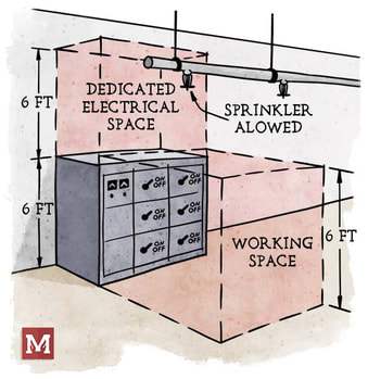 Now are sprinklers in electrical rooms problematic? Generally not (in my experience). Can pipe routing be made to avoid electrical equipment? Usually yes. I try to only run one branch line into the room, most often above the door (since no electrical equipment is on the door), and stick pipe only above walking pathways within the room. 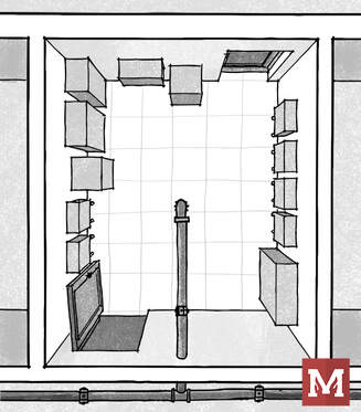 Does the code or standards express any concern or guidance on this? Yes, both the IBC and NFPA 13 address the situation. One line that is included in the IBC specifically says that sprinklers “shall not be omitted from any room merely because it...contains electrical equipment”. To me, that’s a fairly explicit way of suggesting that the presence of electrical equipment alone isn’t a justification for omitting sprinklers. Now there are code allowances and necessary provisions to do so, but the suggestion is not to simply avoid sprinklers just because there is electrical gear. Despite it being awhile since that article, I have had a few requests to make this one into a flowchart, which I’m happy to present today. A special thank you to Alex Riley, PE, who contributed to the code research for this flowchart. 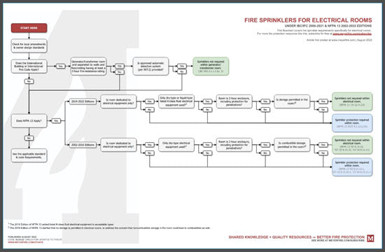
We previously have introduced different types and combinations of threaded fittings - which have been around for more than a century. Here we're introducing another common way to join pipe; using grooved fittings. 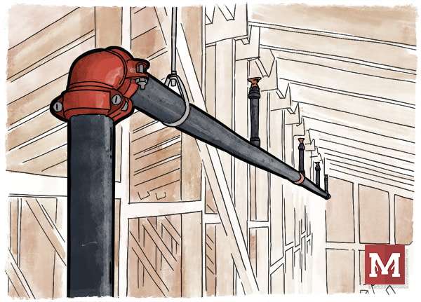 An attic sprinkler system using a grooved elbow with couplings. Use of "mechanical" couplings that could allow faster joining of pipe came to life in 1919 by Lieutenant Ernest Tribe. Just a few years later the Victory Pipe Joint Company renamed itself to Victaulic (a combination of "victory" and "hydraulic"), and grew to expand the technology worldwide. Today, Victaulic and other manufacturing leaders provide grooved fittings that are often used for pipes in fire sprinkler systems. It is not uncommon for both mains and branch lines to be grooved today. What are common grooved fittings, and how do they work? Let's introduce them. 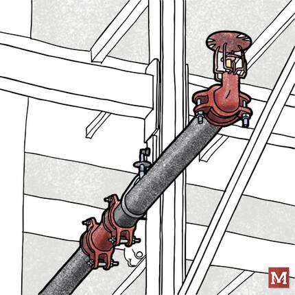 An in-rack sprinkler with a branch line using (starting with the sprinkler) a groove x thread reducing elbow with a grooved coupling, a grooved piece of pipe, and a grooved tee (connection not shown). PIPE Let's start with the pipe. In order to give grooved fittings an opportunity to "grip" the pipe and remain in place, they need an opportunity to resist the pressure of the water that is trying to "pull away" the pipe from the fittings which join them together.  A grooved coupling about to connect two grooved-end pipes. Note the loose nut and bolt on the right-hand side, allowing the coupling to be expanded and "slip" over the pipe on the left. In order to create a groove in the pipe, steel can either be "roll groove" or "cut groove". Roll groove pipe involves pressing an indentation into the pipe near the end of the pipe. This allows a grooved fitting to slip over the end of the pipe and fit into the groove. Roll groove pipe has the advantage of not reducing the pipe thickness, so it can have more tolerance for corrosion than thinner pipe, similar pipe with threads, or pipe with cut grooves. Pipe which is cut groove involves cutting into the pipe rather than pressing it. This cutting removes a portion of the pipe wall, making a thinner but smooth interior pipe wall. This thinner wall makes it more susceptible to corrosion, however, for pipe systems with a minor slope, the smooth inside of the pipe does not create a ridge where water can sit and corrode the pipe. 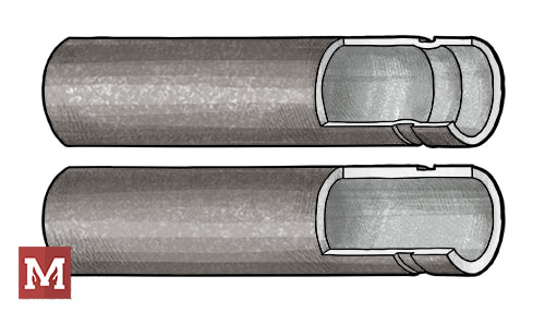 Roll Grooved Pipe (top) and Cut Grooved Pipe (bottom). Note the ridge on the inside of the pipe wall for roll groove pipe, and the thinner pipe wall along the cut groove pipe.  A tape measure with a "go" or "no-go" measurement to determine if the groove is within manufacturer tolerances. ELBOWS & TEES Let's start with the basics. Elbows allow bends of 90-degrees (most common), 45-degrees, 22-1/2 degrees, and 11-1/4 degrees. Why not every possible angle? What if I need to have a 60-degree bend because of my building? First, it wouldn't be economical to make a fitting of every bend. Second, is that using just two 90-degree elbows back-to-back we're able to create a "swing joint" and make any angle we could want, just by changing the elevation of the pipe that's being joined.
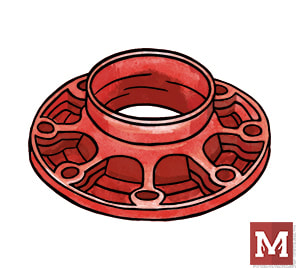
Victaulic "FireLock" Grooved Fittings; 90-Degree Elbow #001 (left), 45-Degree Elbow #003 (center), and Standard Tee #002 (right) One notable specialty with the grooved elbow is a "Drain Elbow", which has the elbow except it includes a drain outlet at the bend of the elbow. This is used all the time with fire department connections which come down a wall and need to be capable of being drained (to avoid having water-charged pipe freeze and burst). This is also called a "Drain-El" or is a Victaulic #10-DR. 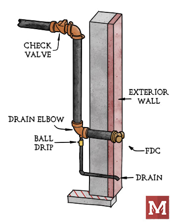 A wall-mounted fire department connection that is away from the riser, here showing the "Drain Elbow" with a ball drip below. The portion upstream of the check valve is intended to be dry unless the FDC is actively being used in order to avoid freezing water inside. COUPLINGS Nice sketches, Joe, but that's not how things look in the field! That's because unlike threaded fittings, the actual pipe joining is by a grooved coupling. The coupling has malleable iron bumps that grip the indent of one groove (pipe/fitting) and connect it to the second groove (the other pipe/fitting). 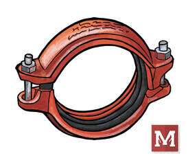 A grooved coupling (here a Victaulic #009N shown). OTHER FITTINGS There are a host of other fitting types. Grooved Reducing Tees? Yep. Less common. Less common can equate to more expensive, or at least that's what I hear from contractors familiar with all the pricing nuances. What other grooved fittings do I often see? Reducing fittings, which is a concentric, single-cast piece of metal that has a large groove on one end and tapers down to a smaller groove on another end. One note of caution is using these in the vertical orientation; I've heard it is much better, more stable, and stronger to use a reducing-fitting as opposed to a reducing-coupling when in a vertical orientation. One of my clients goes so far to say to not use reducing couplings at all (where the coupling itself has two different groove sizes). I wouldn't have the expertise to gauge that myself.
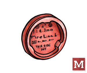
A flange x groove reducer (left) and a grooved cap (right). There are also reducing adapters, than can accept a flange connection and convert it to a reduced groove connection. Crosses are also available, as are caps (like the Victaulic #006 shown above on the right) which can terminate the end of a branch line. These caps even have 1-inch threaded opening options for easy auxiliary drains.  Many manufacturers have equipment and components with grooved ends that can readily attach to pipe and fittings. If you're looking to explore the extend of all available grooved fittings, I'd invite you to check out manufacturer's catalogs or do a simple google search for grooved sprinkler pipe fittings. The manufacturer's product data can do a whole lot of good in clarifying what's been created and listed for use in sprinkler systems. Have tips, tricks, or things to consider about grooved fittings? Comment below. That's all for this week - hope you have a great rest of yours. This week I'm happy to debut an update to one of our popular tools, the K-Factor selector, which is a part of the Toolkit. This tool quickly calculates the actual pressure and flow across different types of sprinklers. It's helpful when we're trying to select the best-possible sprinkler for a hazard. Even for light hazard areas, a standard k5.6 sprinkler may not be the 'optimal' sprinkler, from a hydraulic perspective. We touched on this when looking at whether the flow through a sprinkler is governed by the density and area or by the k-factor and minimum pressure. In short, the minimum flow through a sprinkler can be driven by the coverage area of the sprinkler multiplied by the density of the hazard, or, it can be driven by the k-factor of the sprinkler and the minimum pressure that sprinkler requires.  In either case, it's important to make a quality selection for the k-factor if we want to reduce the required pressure and flow that a system will demand. Less flow usually means less friction loss, which can result in more efficient systems and smaller pipe sizes (saved cost of material and labor).
The updates to this tool make it mobile and tablet friendly, and also now clearly indicate what the 'optimal' sprinkler k-factor is for flow and for pressure (hint: they're not always the same). If you're a Toolkit user, just click the image above to see the updates. Thanks! Last week we debuted a remote area cheatsheet detailing some tips for quick-response reduction, slope adjustments, and dry, double-interlock pre-action and storage area adjustments. We're all about bringing fire protection pros around the world together (globally), and so today I'm happy to also add a metric version of this same cheatsheet. We plan do to updates like this with our content going forward. To download, just click below. If you're a University user, you can get all of our latest cheatsheets, checklists and summaries under your University Dashboard. Thanks & have a great week! 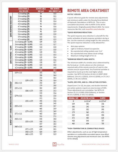 This Remote Area cheatsheet allows for quick adjustments to the remote area and minimum remote-area widths when conducting or reviewing fire sprinkler hydraulic calculations.
It's been too long since our last cheatsheet! Happy to bring about a new one to the table today. One number that I seem to always need to crunch when laying out or reviewing fire sprinkler systems is the remote area adjustments, and the minimum width of a remote area. This applies specifically to the Density/Area method of Hydraulic Calculations in NFPA 13. The formula is simple enough, w = 1.2 x sqrt(remote area size), where w is the minimum remote area width, and the remote area size is our final adjusted remote area that we're using. Now for a routine calculation with a remote area of 1,500 sqft, I pretty much have the 46.5-foot area width memorized. Why is it important? The minimum width dimension tells us how wide our remote area needs to be. It's the dimension parallel to the branch lines, that captures as many sprinklers as it can along the branch line. 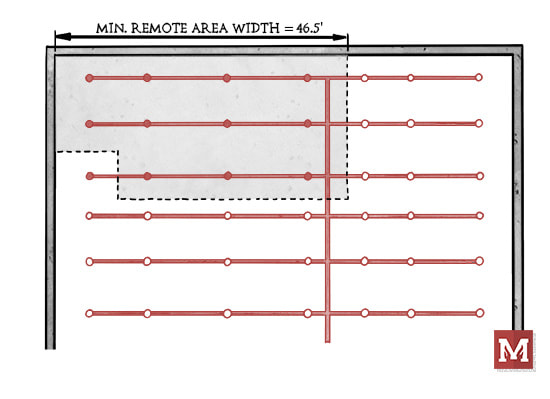 We take this minimum area, see how many sprinklers this area covers, and round up to the next whole sprinkler. It's our minimum width dimension that we're not allowed to reduce. The 46.5-foot dimension might be easy enough to remember, but what about when a remote area is reduced using the quick-response reduction? What if the ceiling is also sloped? Adjustments to the remote area are a process on their own, and each have implications for the minimum remote area width. If you're using our Toolkit you already know we have tools that will compound the calculations for you. Our Quick-Response Reduction tool will adjust the remote area size based on the ceiling height, and our System Estimator tool will adjust for quick-response, sloped ceilings, dry and pre-action systems, high-temperature sprinklers, and more:  But, there are still times where I just want to quickly glance at my remote area size and translate that into a minimum width. That's what today's cheatsheet is all about. This quick reference PDF helps address a few things:
 I hope this one is helpful for you as conduct or review hydraulic calculations on your projects. Any tips, feedback or improvement ideas, be sure to let me know.
Thanks & have a great rest of your week! |

ALL-ACCESS
SUBSCRIBEGet Free Articles via Email:
+ Get calculators, tools, resources and articles
+ Get our PDF Flowchart for Canopy & Overhang Requirements instantly 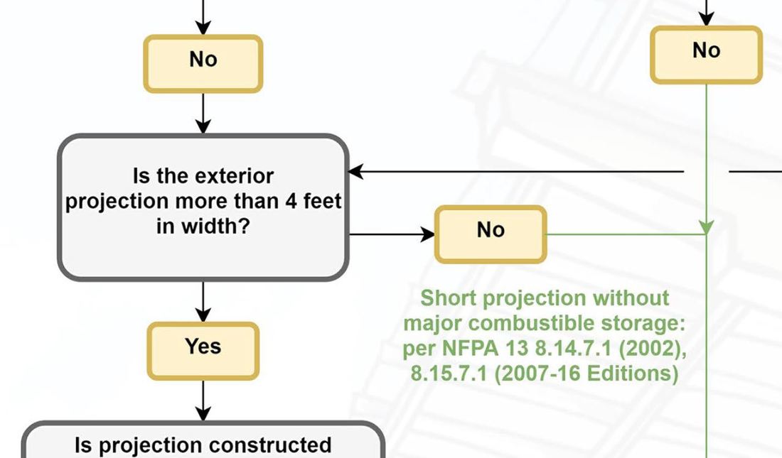
+ No spam
+ Unsubscribe anytime AUTHORJoe Meyer, PE, is a Fire Protection Engineer out of St. Louis, Missouri who writes & develops resources for Fire Protection Professionals. See bio here: About FILTERS
All
ARCHIVES
May 2024
|


 RSS Feed