
|
I've come across this question - why do we need to flow more water - from two angles: as a total rookie, and later on as someone needing to really understand a water supply.
As a newbie - I was intimidated by a few things; first, that someone would call the police on me because I didn't look like I knew what I was doing. Second, that I didn't want to destroy any landscaping. And third, I definitely didn't want to be breaking any hydrants. Those three factors made me want to keep my flow tests as calm and low-flow as possible. However, as I was told at the time, that's not advantageous when we're trying to determine the quality of an existing water supply. Just a year ago, I was working on a project with a marginal water supply, where the water tower and the pumps feeding it were controlled by the project owner. The tower was in some disrepair (not known to us at the time), and we were trying to figure out why we were getting such different results from what should have been a fairly consistent supply. It was on this project where we really needed to understand the strength of the supply that was well beyond just 300, 400, or 500 gpm into the system. But why? Why does it matter if we flow 500 gpm or 1,000 gpm when doing a flow test? One perspective - and one answer to this - is confidence in the data. We gain more confidence in our test results with the greater amount of water we flow. Here's a video we put together that explains this perspective a little better:
Hope you have a great week!
I have a little different spin on things this week that I'm excited to share.
Last month I wrote a bit about flow coming from hydrants and included PDF flow charts relating the measured pitot pressure to the estimated flow coming from the orifice. But what is a Coefficient of Discharge? Check out this new video below - it is a sample from our MeyerFire University platform that we're creating for later this fall. If you don't see the video, click here. This is all new format for this site, so I'm eager to hear what you think. Comment below or shoot me an email at [email protected]. Thanks and have a great rest of your week!
The fire sprinkler database is coming up on its third year in existence; it originally took hundreds of hours of research and plenty of updates, but we're happy to say now that we've upgraded the database to include better search, sort and filter capabilities.
The database is a collection of over 1,500 fire sprinkler models on the market today. Even with a select number of manufacturers, finding just the right type of sprinkler with correct spacing and minimal pressure demands can be tough. The database was built to get answers in seconds - with links directly to manufacturer websites & data sheets. See a quick update video here: The database is part of our Toolkit package. More information about that here. Have a great rest of your week! Drainage from a fire sprinkler system can often be overlooked as it does not directly fight the fire. However, those involved in inspections & testing of sprinkler systems know all too much about how poor drain design for a sprinkler system can negatively impact how tests are conducted, how long it takes a system to drain, and what messes building owners have to deal with. Here are various components for drains on a sprinkler system, and some of the common requirements that pair with them.  For best viewing of the table below, click here: requirements-for-drains-in-fire-sprinkler-systems.html
Most of my articles don't necessarily break new ground - and that's intentional. There are a lot of people smarter than myself who volunteer for many years to contribute to the codes and standards we have today. My role, as I've seen it for some time, is helping share lessons learned and my understanding of those topics. When we share our knowledge, we all help create a world a little more safe from fire. After writing off and on for five years now (woah!), I finally have something that might be a new contribution to the industry. Not in a real or tangible way, but something that may just not have been thought about exactly like this before. I've asked around and I haven't seen this concept out in the world before, so I think this could be something new. It could also have very well been thought about and published 30 years ago and just got buried in history. If so, I'll disclaim credit. My father in-law is a mechanical engineer in research and product development, and for years he's help spur ideas and help kick around new things to try. He once said (perhaps jokingly) that to really make a dent in the world you have to name some kind of industry contribution after yourself. Well, today's the day. I'm calling this concept the Meyer Box. I know, I know. This is so profound and earth-shattering. I'm so glad I've come up with such a great name for what could be my only real new-ground breakthrough to date. Also, if there aren't enough things named Meyer-something around here, I felt it my duty to throw yet another thing into the mix. So if you were itching for more Meyer, then my friend today is your day. The concept started with the way we lay out smoke detectors. We're allowed to space smoke detectors 30-feet apart, or, as an alternative, any location as long as all points within a room are within 21-feet. I wrote an article about this (often-overlooked) method some time ago. Sprinkler spacing follows similar logic; except there is an allowable coverage area, per sprinkler, and a maximum spacing that sprinklers can be apart. Why isn't there some shape for a sprinkler, that if all floor areas are covered in it, that protection is appropriate? Like all my typical daydreaming, I immediately was forced to spend the rest of the billable hours that day jumping further and further down a wormhole of algebra and confusion. If you've ever worked with an architect on a sprinkler layout, you know they love to draw circles around sprinklers and spot-the-dot in a very crude way. Is it accurate? No. Does it meet code? No. Does it get them where they need to go? Not really, but they seem to think so. If a circle doesn't work, there's got to be some natural geometric relationship (a shape) that would work. That's when I got to experimenting and back to some basic math. Light Hazard Light Hazard rules are basic, and they result in a basic shape. Non-combustible (or combustible unobstructed) standard spray upright & pendent sprinklers get 225 sqft per sprinkler, and a maximum spacing of 15-feet according to NFPA 13.  First, I drew a sprinkler (above). Next, I copied the sprinkler to the maximum spacing for Light Hazard, 15-feet to the right:  What is the maximum distance these two sprinklers can be copied vertically and not be overspaced? For Light Hazard, that's easy - 15-feet. The 15-ft x 15-ft spacing is exactly 225 sqft total, which is right at the maximum spacing per sprinkler:  Now, if we attribute sprinkler coverage to each of these sprinklers, the dividing line would simply be the midpoint between each sprinkler, effectively creating just a 15-ft x 15-ft box around each sprinkler.  For light hazard, this "box" is easily understood, and is basic. Things get more interesting when our coverage area is limited to 130 square feet per sprinkler, like we often see for Ordinary Hazard. Ordinary Hazard Using the same approach, let's start with a single sprinkler, ad then copy to a maximum spacing of 15-feet to the right:  Now, in order to not exceed 130 square feet per sprinkler, what is the maximum these two sprinklers can be spaced in the opposite direction? That would be 130 sqft / 15-feet, or 8.67-feet to the north:  Now for the sake of trying to attribute an area to each sprinkler, let's identify the exact intersection of coverage between these four sprinklers. It would be the midpoint of all four sprinklers, here:  Note here that if the north-to-south distance was less than 8'-8", we would still have compliant coverage. This is the maximum spacing between these sprinklers to still accommodate 130 sqft per sprinkler. But what if our spacing in the east-west direction was less than 15-feet? Say it's 13-feet. Here's where that new midpoint lands:  Keeping that original sprinkler in the same place, we can repeat this process over and over again re-spacing the other three sprinklers in their maximum configuration:  If we keep running this process over and over, we start to see a trend in how this boundary exists:  Around each sprinkler, there's a natural boundary line, where if every sprinkler's box covers the floor area, then the 130 sqft-per-sprinkler coverage area is met.  This new box around the original sprinkler is what we're talking about. If this box stays with each sprinkler, then as long as all of the floor area is covered within a sprinkler's box, the coverage rules are met. Let's look at what this does practically when laying out sprinklers:  Why would this be helpful? For one, you can now instantly see whether a layout adequately covers all floor areas. Think less dimensioning and hand-calculating whether a sprinkler is overspaced at 130 sqft. For two, as you're laying out a system, it's easy to snap to the maximum opposite dimension. In the video above, I entered in 13-feet in the east-west direction, and 10-feet in the north-south direction. That's 130 sqft per sprinkler. However, with this box I could also just select the box and copy from the intersection of the boxes.  Above, this would be a code-compliant layout. There are no gaps in these coverage boxes. There are exceptions to this to watch, though. Irregular boundaries might be inside a coverage box, but would exceed the maximum spacing or 130 sqft for the sprinkler.  These are exceptions though, and don't come up often. When I lay out sprinklers I evaluate these one-off scenarios when they crop up, and address them at that time. Could the same shape be performed for a 100 sqft limitation? Yes, it can. Here's what a 100 sqft limit with 12-ft max spacing would look like:  Mathematically, how are these curves defined? If a sprinkler is at (0,0) on an X-Y coordinate graph; to get any Y-coordinate on the 130 sqft box the equation would be Y = 32.5 / X (where X is the X-coordinate, and is between 4.3 and 7.5). Why is this a power function? Simple - X x Y = 130 sqft. If we're drawing a curve to represent one-fourth of the overall area, then we take X x Y = 130 / 4, or, rearranged, Y = (130/4x) = 32.5 X. Where would we draw the line for the 100 sqft box? Similar premise: Y = 25 / X (where X is the X-coordinate, and is between 3.9 and 6) Importance Why is this relevant? Having coverage boxes for sprinklers can be a huge time saver if used appropriately. Model these in CAD blocks or Revit families and the time saved on sprinkler layouts and review alone could be major. How do I draw these up? Are there familes or CAD blocks I can use? Yes - I've drawn these myself and uploaded the files for paid members here. Just login and download these files. Feedback
Have you used anything similar before? What are your thoughts? Comment on the blog here (www.meyerfire.com/blog) or shoot me an email at [email protected]. Always interested in your take. Have a great rest of your week! A year ago I published an updated flowchart on fire sprinkler requirements for Porte-Cocheres, Canopies & Overhangs under NFPA 13. Since then I've had a few requests for sprinkler requirements for Balconies that are under NFPA 13R. Today I'm happy to say that it's finally here; a cheatsheet for when a sprinkler is required for balconies, porches, and other similar exterior projects for NFPA 13R. Take a look and let me know what you think! 
We believe that shared knowledge and sharp resources make for better fire protection all around. Our goal here at MeyerFire is to help fire protection professionals thrive, which in turn makes a more informed, safer world and a better industry all-around. That really is our credence. I plan to talk a little more on that next week, but for this one I hope you have a great rest of your week! Keep fighting the good fight. A quick update this week - back in 2018 I put together a flowchart for when sprinklers are required in closets. It was nice and had some nice feedback, but it only pertained to the 2016 Editions of NFPA 13, 13D, and 13R. This week I went back and made some major updates for references from the 2002 through the 2019 Editions for each of these standards. This cheatsheet is a little more printer-friendly (11x17) and simplified to the NFPA 13, 13D and 13R standards. 
If you're a fan of these cheatsheets and flowcharts, check out the Toolkit. For a limited time we've set up an instant-download of all the latest cheatsheets immediately when you subscribe. If you're already a subscriber, great! Just login for the link. Hope you have a great rest of your week! Quick but big post today - we've just completed our most-requested tool to date - I'm happy to announce the System Estimator. We've taken the Remote Area Analyzer (free online, here), added in hose allowances, main losses, elevation losses, riser details, and underground for an estimator tool that allows k-factor, spacing, density, system type, etc with updated system pressure and flow demands, all in real-time! Check out a very rough video snapshot of real-time pressure and flow updates here: If you're a toolkit subscriber - great! Get the new tool right now by clicking the download link below: Have you ever needed to do a quick estimate for a job, and not had a couple spare hours to lay out and calculate a system?
Even for a very basic remote area, laying out sprinklers & pipe, adding fitting, flow, control valve, and backflow losses, a source, and then hydraulically calculating is smoothly - easily can take an hour or more. Now take that same design and change it to a dry system, or at a different density. If you're like me, tweaking sprinkler spacing, k-factors, sprinkler heights, remote area sizes, and c-factors alone can take significant iteration just to get an idea of pressure & flow demand. With this new estimator you can adjust all of those items in one-click, and see the immediate impact of each decision. It's built for estimators, but it can be a very helpful tool for new designers & engineers to quickly grasp design decisions well before a system has to be completely laid out and detailed. Any feedback, let me know! As always, thanks for reading & have a great rest of your week. If you work in and out of the residential design space, you may come across this question quite a bit. A couple of years ago I wrote on this topic and put together a brief summary of the differences from a design and code perspective. This one gained a lot of traction and attention, and was included in the National Fire Sprinkler Magazine's Member takeover in the September/October 2020 Edition. An updated cheatsheet is attached and includes some great feedback I've had since that 2018 article. Thanks & hope you have a great weekend! 
Awhile back I mentioned there were some big projects in the works around here. This has been Number 1 on my list for over a year now. Last summer I threw out an idea that took hold, and since last November I've been thrilled to be a part of a project that I think will be a major help for industry professionals. The National Fire Sprinkler Association (NFSA) has published informal opinions on everything fire sprinklers for longer than I've been alive. Their Expert of the Day program answers real questions to the 'gray' areas of code with practical advice from leading industry experts. While these opinions have been collected and published monthly for decades, up until now they've never been assembled, organized, and published into a single resource. I'm thrilled to announce that this collection of expertise is now complete; the NFSA Expert of the Day Handbook is a two-volume, hardcover set of over 1,300 pages covering nearly 2,000 questions on over 585 topics relevant to fire sprinkler systems, standpipes, water supplies, inspection, testing, maintenance, codes and standards.  Why am I so thrilled about it? I had the pleasure to work with NFSA by collecting, converting, and organizing all the expert inputs into these volumes. This was a concept I really wanted to see happen - and after sharing the idea of compiling the years of content to NFSA they were happy to fold me into the team on this project. It's now available for pre-sale with shipments starting in just a few weeks (late August / early September). If you are a sprinkler designer, engineer, inspector, installer, plan reviewer, code authority, or work in and around the fire sprinkler industry, then this handbook was built for you. Just in the eight months of reading and compiling the information I saved days of code research (thousands of dollars in billable hours) by having quick access to these expert opinions. Just as it is part of the mission of this site, I am wholeheartedly excited to see how these handbooks help promote best practices and share expertise with the industry. Check out more about this two-volume 1,300 page set and get a copy today. Questions? Comments? Shoot me a line at [email protected]. |

ALL-ACCESS
SUBSCRIBEGet Free Articles via Email:
+ Get calculators, tools, resources and articles
+ Get our PDF Flowchart for Canopy & Overhang Requirements instantly 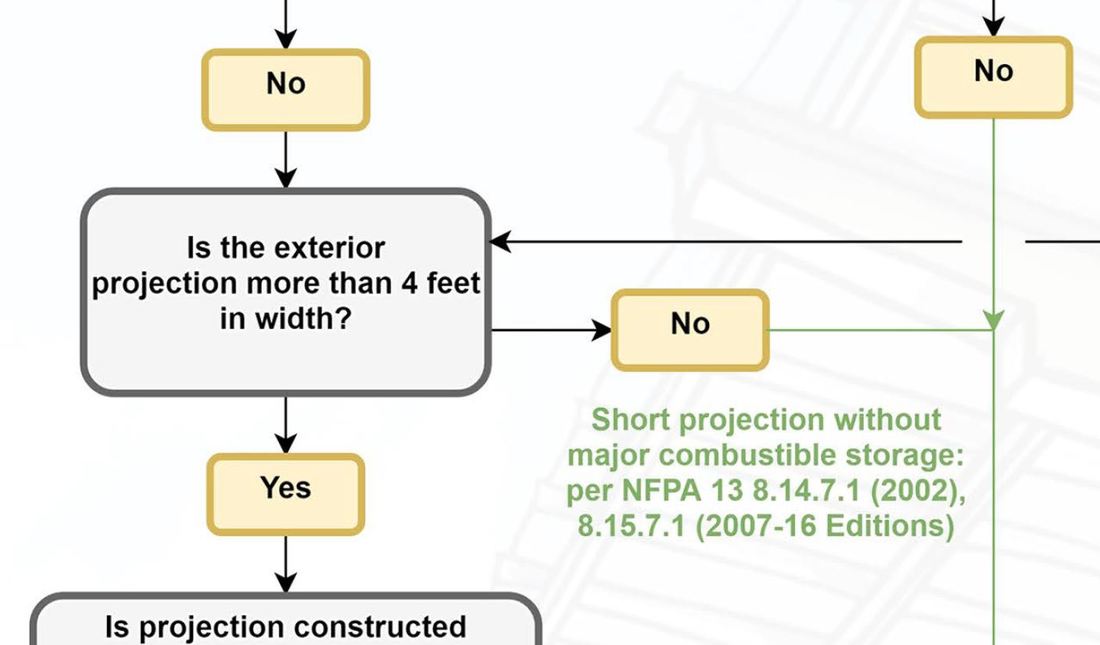
+ No spam
+ Unsubscribe anytime AUTHORJoe Meyer, PE, is a Fire Protection Engineer out of St. Louis, Missouri who writes & develops resources for Fire Protection Professionals. See bio here: About FILTERS
All
ARCHIVES
July 2024
|
 RSS Feed