
|
Drainage from a fire sprinkler system can often be overlooked as it does not directly fight the fire. However, those involved in inspections & testing of sprinkler systems know all too much about how poor drain design for a sprinkler system can negatively impact how tests are conducted, how long it takes a system to drain, and what messes building owners have to deal with. Here are various components for drains on a sprinkler system, and some of the common requirements that pair with them.  For best viewing of the table below, click here: requirements-for-drains-in-fire-sprinkler-systems.html
We're back this week with an overview of Pressure Gauges in Fire Suppression Systems. NFPA 13, 14, and NFPA 20 provide guidance on where pressure gauges are required, and recommendations for various aspects around pressure gauges. This week's checklist includes various aspects and code references all-around pressure gauges. What tips & tricks would you recommend surrounding pressure gauges based on your experience? Let us know here.
For more articles like this, subscribe here. Thanks & have a great rest of your week!
For those ready to take on the Practice & Principles of Engineering (PE) Exam this year, it's about that time again! Weather is getting warmer, the kids are about ready to get out of school, and we're getting our weekly dose of SFPE course emails - time to get started! Around here we're excited to introduce a different twist on a favorite - we're turning our daily free sample problems into an on-demand series, with instant solutions. If you're interested in getting 100 days of free Fire Protection PE Exam sample questions, sign up here:  If you're just curious and want the challenge - go for it! If you are suiting up for the PE Exam this year, be sure to check out what we've got going:  2021 PE PREP GUIDE The 2021 Edition of the PE Prep Guide is hot off the press and is shipping out daily. This new edition now includes the PE Roadmap written by our friends at the BuildingCode.Blog, which is a full-length study schedule, study topics, and suggested readings for a full-blown self-study program. There's also a condensed study schedule as well. That's all now included with the PE Prep Guide. THE PE PREP SERIES The PE Prep Series is starting up next week. Last year over 85 participants took part in the 20-week online series, which includes a timed mini-exam of 10 questions each week. Check it out here and join us as the summer competition heats up.  [NEW] PE ROADMAP VIDEO SERIES
Lastly - an announcement I'm very excited is finally here. After many requests we finally have an online series of videos that work through Prep Series solutions by hand. That's over 200 hand-worked solutions and 30+ hours of helpful content. It's developed and run by our friends at the Building Code Blog, and we couldn't be more excited that this new resources is now available for the Fire Protection PE Prep space. See more about it here. Any questions, shoot them my way at [email protected]. Hope you have a great rest of your week! Most of my articles don't necessarily break new ground - and that's intentional. There are a lot of people smarter than myself who volunteer for many years to contribute to the codes and standards we have today. My role, as I've seen it for some time, is helping share lessons learned and my understanding of those topics. When we share our knowledge, we all help create a world a little more safe from fire. After writing off and on for five years now (woah!), I finally have something that might be a new contribution to the industry. Not in a real or tangible way, but something that may just not have been thought about exactly like this before. I've asked around and I haven't seen this concept out in the world before, so I think this could be something new. It could also have very well been thought about and published 30 years ago and just got buried in history. If so, I'll disclaim credit. My father in-law is a mechanical engineer in research and product development, and for years he's help spur ideas and help kick around new things to try. He once said (perhaps jokingly) that to really make a dent in the world you have to name some kind of industry contribution after yourself. Well, today's the day. I'm calling this concept the Meyer Box. I know, I know. This is so profound and earth-shattering. I'm so glad I've come up with such a great name for what could be my only real new-ground breakthrough to date. Also, if there aren't enough things named Meyer-something around here, I felt it my duty to throw yet another thing into the mix. So if you were itching for more Meyer, then my friend today is your day. The concept started with the way we lay out smoke detectors. We're allowed to space smoke detectors 30-feet apart, or, as an alternative, any location as long as all points within a room are within 21-feet. I wrote an article about this (often-overlooked) method some time ago. Sprinkler spacing follows similar logic; except there is an allowable coverage area, per sprinkler, and a maximum spacing that sprinklers can be apart. Why isn't there some shape for a sprinkler, that if all floor areas are covered in it, that protection is appropriate? Like all my typical daydreaming, I immediately was forced to spend the rest of the billable hours that day jumping further and further down a wormhole of algebra and confusion. If you've ever worked with an architect on a sprinkler layout, you know they love to draw circles around sprinklers and spot-the-dot in a very crude way. Is it accurate? No. Does it meet code? No. Does it get them where they need to go? Not really, but they seem to think so. If a circle doesn't work, there's got to be some natural geometric relationship (a shape) that would work. That's when I got to experimenting and back to some basic math. Light Hazard Light Hazard rules are basic, and they result in a basic shape. Non-combustible (or combustible unobstructed) standard spray upright & pendent sprinklers get 225 sqft per sprinkler, and a maximum spacing of 15-feet according to NFPA 13.  First, I drew a sprinkler (above). Next, I copied the sprinkler to the maximum spacing for Light Hazard, 15-feet to the right:  What is the maximum distance these two sprinklers can be copied vertically and not be overspaced? For Light Hazard, that's easy - 15-feet. The 15-ft x 15-ft spacing is exactly 225 sqft total, which is right at the maximum spacing per sprinkler:  Now, if we attribute sprinkler coverage to each of these sprinklers, the dividing line would simply be the midpoint between each sprinkler, effectively creating just a 15-ft x 15-ft box around each sprinkler.  For light hazard, this "box" is easily understood, and is basic. Things get more interesting when our coverage area is limited to 130 square feet per sprinkler, like we often see for Ordinary Hazard. Ordinary Hazard Using the same approach, let's start with a single sprinkler, ad then copy to a maximum spacing of 15-feet to the right:  Now, in order to not exceed 130 square feet per sprinkler, what is the maximum these two sprinklers can be spaced in the opposite direction? That would be 130 sqft / 15-feet, or 8.67-feet to the north:  Now for the sake of trying to attribute an area to each sprinkler, let's identify the exact intersection of coverage between these four sprinklers. It would be the midpoint of all four sprinklers, here:  Note here that if the north-to-south distance was less than 8'-8", we would still have compliant coverage. This is the maximum spacing between these sprinklers to still accommodate 130 sqft per sprinkler. But what if our spacing in the east-west direction was less than 15-feet? Say it's 13-feet. Here's where that new midpoint lands:  Keeping that original sprinkler in the same place, we can repeat this process over and over again re-spacing the other three sprinklers in their maximum configuration:  If we keep running this process over and over, we start to see a trend in how this boundary exists:  Around each sprinkler, there's a natural boundary line, where if every sprinkler's box covers the floor area, then the 130 sqft-per-sprinkler coverage area is met.  This new box around the original sprinkler is what we're talking about. If this box stays with each sprinkler, then as long as all of the floor area is covered within a sprinkler's box, the coverage rules are met. Let's look at what this does practically when laying out sprinklers:  Why would this be helpful? For one, you can now instantly see whether a layout adequately covers all floor areas. Think less dimensioning and hand-calculating whether a sprinkler is overspaced at 130 sqft. For two, as you're laying out a system, it's easy to snap to the maximum opposite dimension. In the video above, I entered in 13-feet in the east-west direction, and 10-feet in the north-south direction. That's 130 sqft per sprinkler. However, with this box I could also just select the box and copy from the intersection of the boxes.  Above, this would be a code-compliant layout. There are no gaps in these coverage boxes. There are exceptions to this to watch, though. Irregular boundaries might be inside a coverage box, but would exceed the maximum spacing or 130 sqft for the sprinkler.  These are exceptions though, and don't come up often. When I lay out sprinklers I evaluate these one-off scenarios when they crop up, and address them at that time. Could the same shape be performed for a 100 sqft limitation? Yes, it can. Here's what a 100 sqft limit with 12-ft max spacing would look like:  Mathematically, how are these curves defined? If a sprinkler is at (0,0) on an X-Y coordinate graph; to get any Y-coordinate on the 130 sqft box the equation would be Y = 32.5 / X (where X is the X-coordinate, and is between 4.3 and 7.5). Why is this a power function? Simple - X x Y = 130 sqft. If we're drawing a curve to represent one-fourth of the overall area, then we take X x Y = 130 / 4, or, rearranged, Y = (130/4x) = 32.5 X. Where would we draw the line for the 100 sqft box? Similar premise: Y = 25 / X (where X is the X-coordinate, and is between 3.9 and 6) Importance Why is this relevant? Having coverage boxes for sprinklers can be a huge time saver if used appropriately. Model these in CAD blocks or Revit families and the time saved on sprinkler layouts and review alone could be major. How do I draw these up? Are there familes or CAD blocks I can use? Yes - I've drawn these myself and uploaded the files for paid members here. Just login and download these files. Feedback
Have you used anything similar before? What are your thoughts? Comment on the blog here (www.meyerfire.com/blog) or shoot me an email at [email protected]. Always interested in your take. Have a great rest of your week! A year ago I published an updated flowchart on fire sprinkler requirements for Porte-Cocheres, Canopies & Overhangs under NFPA 13. Since then I've had a few requests for sprinkler requirements for Balconies that are under NFPA 13R. Today I'm happy to say that it's finally here; a cheatsheet for when a sprinkler is required for balconies, porches, and other similar exterior projects for NFPA 13R. Take a look and let me know what you think! 
We believe that shared knowledge and sharp resources make for better fire protection all around. Our goal here at MeyerFire is to help fire protection professionals thrive, which in turn makes a more informed, safer world and a better industry all-around. That really is our credence. I plan to talk a little more on that next week, but for this one I hope you have a great rest of your week! Keep fighting the good fight. One of the most-requested tool features was not technical - we wanted color! I'm happy to say that with today's new updated release of the MeyerFire Toolkit we now have just that - different color options to match your company's look:  It sounds incredibly simple, but this one took a little while to work out the kinks. At least we rocked out to 90's jock jams while doing the updates, which may or may not have influenced the bright color choices. To get this update, download the latest version of the Toolkit here: www.meyerfire.com/download. If you aren't a Toolkit user, you can get a copy here - www.meyerfire.com/toolkit. Thanks & have a great week! A quick update this week - back in 2018 I put together a flowchart for when sprinklers are required in closets. It was nice and had some nice feedback, but it only pertained to the 2016 Editions of NFPA 13, 13D, and 13R. This week I went back and made some major updates for references from the 2002 through the 2019 Editions for each of these standards. This cheatsheet is a little more printer-friendly (11x17) and simplified to the NFPA 13, 13D and 13R standards. 
If you're a fan of these cheatsheets and flowcharts, check out the Toolkit. For a limited time we've set up an instant-download of all the latest cheatsheets immediately when you subscribe. If you're already a subscriber, great! Just login for the link. Hope you have a great rest of your week! Quick but big post today - we've just completed our most-requested tool to date - I'm happy to announce the System Estimator. We've taken the Remote Area Analyzer (free online, here), added in hose allowances, main losses, elevation losses, riser details, and underground for an estimator tool that allows k-factor, spacing, density, system type, etc with updated system pressure and flow demands, all in real-time! Check out a very rough video snapshot of real-time pressure and flow updates here: If you're a toolkit subscriber - great! Get the new tool right now by clicking the download link below: Have you ever needed to do a quick estimate for a job, and not had a couple spare hours to lay out and calculate a system?
Even for a very basic remote area, laying out sprinklers & pipe, adding fitting, flow, control valve, and backflow losses, a source, and then hydraulically calculating is smoothly - easily can take an hour or more. Now take that same design and change it to a dry system, or at a different density. If you're like me, tweaking sprinkler spacing, k-factors, sprinkler heights, remote area sizes, and c-factors alone can take significant iteration just to get an idea of pressure & flow demand. With this new estimator you can adjust all of those items in one-click, and see the immediate impact of each decision. It's built for estimators, but it can be a very helpful tool for new designers & engineers to quickly grasp design decisions well before a system has to be completely laid out and detailed. Any feedback, let me know! As always, thanks for reading & have a great rest of your week. The community here is second to none - after a post on my personal list of ideas for getting 'unstuck' in hydraulic calculations last week, I received a handful of encouraging emails and a string of great commentary. Being an engineer and a son of two accountants, I can't help but turn those everything into a spreadsheet. With the tips last week and great feedback sent in, here is a PDF tipsheet that includes a quick rundown of ideas to consider when fine tuning and getting 'unstuck' while running fire sprinkler hydraulic calculations. Click the image or link below to download. 
If you haven't already subscribed for tools & cheatsheets like this, you can do so, for free, here. Thanks & have a great rest of your week! Have hydraulic calculations ever kept you up at night?
I can usually tell when I’m carrying extra stress in my life because my nightmares looks suspiciously like a hydraulic calculation that, despite any refinement, just doesn’t calc’ out. Ever had that? I’ll refrain from sharing all my personal issues for now, but if you’re a sprinkler designer or FPE, you’ve had to experience a project where there’s seemingly no way to get the hydraulics in the black. When I initially lay out a project I’ll have a rough idea of pipe sizing and layout type (tree, grid, loop) based on similar projects. I’ll lay out a remote area and ‘rough-in’ the rest of the design so that I can get to hydraulic calculations iterations as early as possible. Iterations? Yes, iterations. If you’re long versed in the sprinkler industry this needs no explaining. If not, the secret sauce of a high-value designer/engineer is all in the refinement and iterations. If you’re a consulting engineer, perhaps you’re less interested in whether a system is efficient and more interested in whether a system ‘can work’. If you’re on the install side of the trade, you can earn back good pay and more by calculating systems that are well optimized – that is – perform efficiently, use the right system type, sprinkler type, and allocate pipe sizing appropriately. This week I’m running down a quick list on potential avenues to consider when you’re working through those calculations and need ideas on tweaks that could help. A quick disclaimer – hydraulic calculations are an important part of ensuring that the systems we design will be effective in suppressing a fire. The categories below are important aspects to consider when conducting hydraulic calculations – not corners to cut – but rather ideas to get unstuck in optimizing a sprinkler system. System Type Probably most important consideration is the system type (grid, loop, or tree). Dry and pre-action systems have limitations (no grids allowed), but if a facility is big enough then moving to a loop or grid configuration may significantly help the system perform more efficiently (ie: smaller size pipe). Sprinkler K-Factor This perhaps could be the most often-overlooked impact on a sprinkler calculation. Are you using the right k-factor for the job? If you’re always using K5.6 until you get into storage applications – there are better tools for the trade. Adjusting the k-factor based on the density and sprinkler spacing directly impacts the starting pressure within a hydraulic calculation. If you haven’t tried it yet, use this tool that’s a part of the Toolkit to find the optimal k-factor for your job. Pipe Sizing Perhaps the most obvious and classic go-to is adjusting the size of pipe diameters. The larger the pipe diameter, the easier (less friction loss) the water will experience when passing through the pipe. Pipe Schedule This isn’t always negotiable – many specified projects will stipulate a pipe wall thickness – but be cognizant that the pipe schedule is (1) correct for the job, and (2) is considered in the hydraulic calculations. I had long underestimated the impact that pipe schedule had on hydraulic calculations, but it’s major. Schedule 40 and Schedule 10 can have a major impact. Change from Schedule 10 to Schedule 40 and you’ll increase friction loss by 24%. See the impact on friction loss with the Friction Loss Calculator as part of the Toolkit here. C-Factor Also not a negotiable part of a project – c-factor directly relates to the friction loss under the Hazen-Williams method of hydraulic calculations – its nonetheless important to get correct. How can you improve the c-factor? The pipe type (plastic, copper, ductile iron or steel) and system type (wet, dry, pre-action, deluge) will impact the c-factor. One project I worked on had major challenges, including a quadruple-slam of dry system, sloped roof, tall roof, and poor water supply. The only suggestion we had to avoid a fire pump was to insulate and heat the building such that a wet system could be used. That change had a number of impacts, but the c-factor change from 100 to 120 for the pipe had a major bearing on the new system working. One major change that’s coming to the 2022 Edition of NFPA 13 is allowing a C-Factor of 120 to be used on new dry systems that are installed with nitrogen. I’ll be sure to explore this in more depth when the time comes. Sprinkler Spacing Are your sprinklers maxed out at the greatest possible coverage area? In some applications, this can hurt more than it helps. Yes, we might save on the cost of material and labor with a reduction in sprinklers, but reducing the area per sprinkler in a very tight calculation can have a positive impact with starting pressures and the densities achieved. See the density vs. k-factor calculator as part of the Toolkit to see the impact with various sprinkler spacings. Remote Area Size There are some reductions in allowable remote area size in NFPA 13. A common one is the quick-response reduction, which allows a smaller remote area size for systems which have low(er) ceilings and quick-response sprinklers. See the impact of remote area with the Remote Area Analyzer here. Water Source Height An often overlooked part of the calculation that has a major bearing on the result is the height of the water source. Many systems are designed based on a fire hydrant flow test. Is the elevation of that source accurate, relative to the jobsite? I once worked on a job where a submittal showed the source (city water grid) to be at an elevation of 0'-0" relative to the first floor of the building. I charted google earth and paid close attention to the listed source from the flow test report. While a hydrant existed about at ground level elevation, the actual static/residual hydrant where the test results were gathered was at an elevation 27-feet below the project grade. It was a substantial hit to the hydraulic calculations (all calculations failed with the correct elevation shown). Backflow Preventer Loss On many systems the backflow preventer presents the worst pressure loss for any single piece of equipment on the system. It's easy as a designer to input a curve or a conservative static loss, run the calculation, and not return to the backflow preventer. However, if you're seeing high pressure losses, shop around. There are a variety of backflow preventers on the market, and using backflows that are straight (horizontal/vertical, not N- or Z-type) and use OS&Y valves instead of butterfly valves can offer some hydraulic savings. There's a whole database we've created on available backflow preventers as part of the Toolkit here: BACKFLOW DATABASE* Valve Types Just like backflow preventers, valves introduce pressure loss into the system. An OS&Y valve will remove the water-blocking paddle from the water stream, allowing water to pass through mostly unimpeded. Other valves like butterfly valves leave the paddle in place, causing some pressure loss. Sprig, Drop, On-Pipe, Flexible Drop & Return-Bend Configurations Ever looked at the difference between using sprigs and not using sprigs (on-pipe fittings or outlets) has on a calculation? If you're at a higher density, it can be significant. Hydraulic calculations are usually not a driver in whether sprigs are used, or whether return-bends vs. side outlets vs. bottom drops are incorporated - however - these have an impact on the calculations and can introduce pressure loss in between the sprinkler and the branch pipe. One notoriously high friction loss arena is use of flexible drops, which can add pressure loss with equivalent 1-inch pipe lengths of 20-70 feet of pipe. These friction losses can vary significantly among manufacturers and models. Riser Nipple & Sprig Diameters Have a storage calculation with high densities and a high sprinkler k-factor? It may be worth adjusting the sprig diameter to see the impact of the 1-inch diameter pipe. Similarly, riser nipples in-between a main and branch line bear the full flow from the branch line to the main. These pieces, while many times shorter than the spacing between sprinklers, can still introduce a pressure loss to the system that a stepped-up diameter can help. Special Application Sprinklers Lastly - is there a sprinkler specifically designed for the application you have? Many manufacturers over many decades have dialed-in and created sprinklers that are built for specific purposes (special application sprinklers). These product listings can allow different starting pressures and design criteria, which, as a whole, can help reduce the water burden on a system. Two that I often use that come to mind are residential and attic special application sprinklers. In both cases, use of those sprinkler types within their respective hazards dramatically reduce the water required at the remote area, thereby allowing smaller mains and equipment back at the riser. See a list of all available sprinklers on the market (filter & search) on the Sprinkler Database in the Toolkit. What Else? In the next post I'll look to put together something that's a little more handy as a checklist for entry and intermediate designers. In the meantime - what am I missing here? What aspect of hydraulic calculations do you think are often overlooked yet carry a big impact? |

ALL-ACCESS
SUBSCRIBEGet Free Articles via Email:
+ Get calculators, tools, resources and articles
+ Get our PDF Flowchart for Canopy & Overhang Requirements instantly 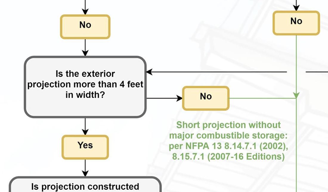
+ No spam
+ Unsubscribe anytime AUTHORJoe Meyer, PE, is a Fire Protection Engineer out of St. Louis, Missouri who writes & develops resources for Fire Protection Professionals. See bio here: About FILTERS
All
ARCHIVES
July 2024
|
 RSS Feed