
|
When conducting or reviewing hydraulic calculations, I very often face scenarios where the initial (very first) hydraulic demand exceeds the potential for the water supply. At that point I lose all hope and add a fire pump to the job. Just kidding, of course - there's at least a half dozen hydraulic elements I analyze and refine to better match the capabilities of the water supply to the design of the sprinkler system. Refining Hydraulic Calculations with K-Factors One of the more fine-tooth aspects I look at is the k-factor used on the sprinklers. The k-factor for a fire sprinkler is the discharge coefficient, or in normal human terms just relates to the amount of water that is permitted through the sprinkler. The k-factor is dependent upon the orifice diameter of the sprinkler - a low k-factor (such as K2.8) restricts the flow of water, while a larger k-factor (such as K22.4, K25.2, or K28.0) permit much more water to flow through. K-factors were originally created to be multiples of the discharge of a K5.6 sprinkler. A K2.8 sprinkler, for example, is 50% discharge of a K5.6 sprinkler, while a K11.2 sprinkler is 200% of the discharge of a K5.6. NFPA 13-2016 Table 6.2.3.1 shows this well.  Use In Design We find K5.6 sprinklers in light hazard all the time. Residential sprinklers often have k-factors less than 5.6. ESFR and CMSA require minimum K11.2 (NFPA 13-2016 6.2.3.5). ESFR are tied directly to the hazard it protects. Back to refining the hydraulics in a system - increasing the k-factor of a sprinkler allows more water to flow through a sprinkler with less pressure loss. This becomes very important when trying to reduce pressure loss in a system. Light Hazard Example A light hazard system (0.10 gpm/sqft) with widely spaced sprinklers (at 225 sqft each) would require a minimum flow through each sprinkler of 22.5 gpm (0.10 gpm/sqft x 225 sqft = 22.5 gpm). In order to flow 22.5 gpm, a sprinkler with a k-factor of 5.6 now requires 16.1 psi to do so (Q=k√p, or rearranged, p=(Q/k)^2). This is 9.1 psi higher than 7 psi, or the minimum that NFPA 13 requires. In order to flow 22.5 gpm, a sprinkler with k-factor of 8.0 only requires 7.9 psi to do so, or less than 1 psi more than the minimum NFPA 13 requires. In this scenario, flowing the same amount of water (22.5 gpm) results in a 8.2 psi difference in the pressure required at the most remote sprinkler. Can 8.2 psi be important? Absolutely! Other Scenarios Similarly, consider Ordinary Hazard Group 1 (0.15 gpm/sqft) and Ordinary Hazard Group 2 (0.20 gpm/sqft) systems. For Ordinary Hazard Group 1 and sprinklers spaced at 130 sqft, a K8.0 sprinkler requires 5.1 psi less than a K5.6 sprinkler (7.0 psi vs 12.1 psi). This same methodology applies to extended coverage sprinkler requirements, specific densities for traditional storage design, and more. The K-Factor Selector Want to quickly compare fire sprinkler k-factors across different design densities and sprinkler spacing? Easy. Here's the calculator I've created that quickly compares pressure requirements and flow rates across different sprinkler k-factors.  Toolkit Update Want all these tools in a downloadable, printable & PDF-saving capability? Great! The MeyerFire Toolkit will include this tool as well. You can download and try it out now through September for free. Sprinkler Database Other than the Toolkit, users of the comprehensive Fire Sprinkler Database can sort & search among k-factors as one of the parameters when comparing sprinklers. Please Share Do you get these articles & tools? If not, follow the fight for better fire protection by subscribing here. Know someone that might be interested in these tools or articles? Please do me a favor and send them a link or email to share these resources. Thanks!
Quick updates for this week - thanks to helpful recent suggestions I've updated the Friction Loss Calculator to include several NFPA 13-provided fittings as well as fluid velocity among various sizes.
With a flow rate and length of pipe, you'll see fluid velocity as it's own column in feet/second. While both NFPA 13 and FM Global do not have any limitations on fluid velocity, it's a good point of reference to reference how quickly a fluid is moving through the pipe. The brief list of fittings at the bottom allow you to compare friction loss across a number of different assembly sizes, so you can compare runs of pipe or assemblies at various sizes all at the same time. Can't see the tool above? See it here: If you don't already get updates on our latest tools and weekly articles, you can get them for free here: Aside from being the historically-preferred location for canine bladder relief, fire hydrants serve an important function in providing access to a water supply system.  Types Fire Hydrants fall within one of two types; wet and dry barrel. Dry Barrel, as implied, is not water-filled until the hydrant valve is opened. Dry hydrants are overwhelmingly the most popular type of hydrant within the United States to provide insulate using depth to prevent freezing portions of the water supply. Wet Barrel hydrants, though infrequent, are used in portions of southern California and Florida. These hydrants have one or more operating stems which run horizontal at each outlet. As implied, wet barrel hydrants are water-filled at all times.  Bonnet The conical cap for the hydrant, or bonnet, holds the operating stem nut in place and protects the hydrant from mechanical damage and water penetration. Branch The branch pipe serving the hydrant from the city main is one restriction for the overall capacity of a hydrant. While older systems often connect hydrants with 4-inch branch pipe, a minimum of 6-inch pipe should be used to limit pressure loss and permit greater flow capacity. Our friction loss tool can be helpful in estimating loss through these pipes. Flange The flange at the base of the hydrant is the point of connection for the hydrant to the rest of the barrel. While the dimension from the bonnet to the flange of the hydrant is standard, the height of the flange becomes important during installation as it determines the height of the outlets. Because hydrants need to be quickly accessed during an active fire, hydrant outlets need to be installed tall enough to allow a full-revolution of a hydrant wrench from the lowest outlet. Hydrant Color Some jurisdictions paint hydrants or hydrant bonnets to identify the capacity of the hydrant. NFPA 291, the Recommended Practice for Fire Flow Testing and Marking of Hydrants, suggests hydrant colors as Red/Class C, Orange/Class B, Green/Class A, and Light Blue/Class AA for Less than 500 gpm, up to 1,000 gpm, up to 1,500 gpm, and 1,500 gpm and more, respectively (NFPA 291-2019 5.2.1.2). Outlets A traditional dry barrel fire hydrant contains three outlets: two 2 1/2-inch (65 mm) side outlets and a single 4 1/2-inch (115 mm) or 6-inch (150 mm) "pumper" outlet. The latter outlet gets its name as it is often the preferred choice for the fire department to connect and feed pumper trucks. The size and number of the outlets serve as one limit to the capacity of the hydrant. While the typical hydrant described above is the most common type, other combinations certainly exist - downtown St. Louis, for instance, have hydrants with only a single pumper outlet. Stem Nut The stem nut is the key to operating the valve within the hydrant. Typically shaped as a pentagon, the stem nut will turn the operating stem of the hydrant and raise the valve to an 'open' position when turned with a hydrant wrench. Thrust Block Unless mechanically restrained, thrust blocks serve as a way to distribute the hydraulic force of the pipe network into the soil. Our thrust block calculator can be helpful in sizing these blocks. Valve When in the 'open' position, the valve at the bottom of a dry barrel hydrant rises to plug drain holes and simultaneously permit water to fill the barrel of the hydrant. When in the 'closed' position, the valve lowers to block water passage and re-open drain holes at the bottom of the hydrant. These drain holes act as weeps which slowly drain the hydrant barrel and help prevent freezing. Follow the Movement
Get these free articles as they're written each week. Follow the movement & get a free sprinkler canopy & overhang requirements guide here: One of the popular aspects of fire sprinkler installations that is overwhelmingly familiar to fitters in the field yet something I hardly understood back as a new graduate is pipe connections. Today I'm breaking out some of the popular methods of joining steel pipe in fire sprinkler systems. Steel Pipe While copper, CPVC and PEX are listed for use in fire sprinkler systems (PEX is only for NFPA 13D systems), black steel pipe remains the most popular pipe material for commercial fire sprinkler applications, at least within the United States. For steel pipe, the primary means of connecting the pipe include threaded fittings, grooved fittings, plain-end compression fittings, flanged connections, and welding. Plain End Pipe Steel pipe when initially formed has flat cut, unpolished ends. This is generally referred to as plain end pipe. Plain end pipe can be connected by compression fittings or push-on fittings, which bite into the pipe to prevent separation. While popular for other building systems, use of plain end pipe and compression or push-on fittings are not used in sprinkler systems due to the relatively high pressures sprinkler systems experience.  Threaded Pipe Perhaps the most common current method of joining fire sprinkler pipe for smaller pipe diameters, threaded pipe makes use of helical crests that screw into a female threaded fitting. To create threaded pipe, a plain-end pipe is cut with a threaded machine decreasing the thickness of the pipe wall. As a result, the areas remaining below and adjacent to the thread become weaker and more susceptible to corrosion breakthroughs with the thinner wall of pipe.  As compared to grooving or welding pipe, the pipe wall thickness must be thicker to accommodate the cut-in threads (ASME B1.20.1) for threaded pipe. NFPA 13 6.5.1.2 (2002-2016 Editions) addresses minimum pipe thicknesses for threaded pipe up to 300 psi, unless the pipe is separately listed for fire sprinkler use:
When connecting threaded pipe, joint compound or pipe tape is applied to the male thread to avoid water leakage. While threading larger pipe was common throughout the early to mid twentieth century, the weight of Schedule 40 pipe and difficulty of turning large diameter threaded pipe makes threading an uncommon choice for larger diameter sprinkler pipe today. Grooved Pipe Grooved pipe is a popular method of pipe joining invented by Victaulic with roots in both World Wars to deliver water and petroleum with faster, more reliable method of pipe connection.  Grooved pipe is formed by either cutting into the pipe (cut groove) or by pressing an indentation into the pipe (roll groove). Cut groove pipe results in a lesser pipe thickness, weakening the pipe and also offering less protection against corrosion. Roll grooving, while keeping the pipe wall thickness, also poses issues in low-sloped dry and pre-action systems as the rolls on the interior side of the pipe create areas to trap water and create an air-water interface for corrosion to occur.  Grooved pipe has a number of inherent advantages. Smaller pipe thicknesses are permitted for grooved pipe, resulting in thinner pipe which makes transporting, carrying, and lifting into place easier. Minimum thicknesses for Grooved Pipe:
With thinner, lighter pipe and easy grooved coupling options, labor can be less difficult and significantly quicker. Welded & Flanged Pipe A less common but additional option for restraining pipe is welding. Pipe can be welded as an outlet - where a welding equipment cuts a hole in one pipe whereafter another pipe segment is held in place and the two are welded together.  Welding has a few advantages - it can be (and often is) performed in a fabrication shop, does not require any additional fittings, and can allow for more custom pipe arrangements. For instance: a 4-inch x 4-inch x 1/2-inch outlet for a pressure gauge connection might be a special order reducing tee (ie: costly); as a welded outlet, it could be quickly and easily welded into place with the outlet easily threaded or grooved. Welding is not limited to outlets, however. "Slip-on flanges" can be welded to the hub side of the flange to a piece of pipe, allowing two flanged fittings to be bolted together with a gasket in-between.  Flanged pipe and fittings are common around fire pump assemblies, as NFPA 20 annex material even notes that "flanges welded to pipe are preferred" despite screwed, flanged mechanical joints or other approved fittings are allowable (NFPA 20 2003-2007 5.13.2.1, 2010-2013 4.13.2, 2016 4.14.2, 2019 4.15.2).
Different installing contractors often have different preferences on fabricating pipe. Personally I've worked with some who prefer to have welded outlets along 21-foot lengths of pipe and groove as much as allowed for a job to use lighter, thinner pipe, including through branch piping. Others prefer some flexibility of threaded pipe to make quick changes in the field and provide a more traditional, tightly-connected threaded system. What do you commonly see? Does your team have preferences for fabrication methods? Discuss this here. Follow the Movement Get these articles, for free, once a week. Follow the movement for better fire protection here.
Last week I introduced a new Thrust Block Calculator and explored some of the concepts around the design and function of Thrust Blocks.
Expanded Calculator Here's the new expanded thrust block calculator. With similar inputs as before, we're now able to calculate the thrust block volume required, as well as determine the height and width required for the thrust block. Toolkit is Here Well it's here! The MeyerFire Toolkit is past a beta version and ready for you. 
Don't Get These Updates? You can subscribe to all the tools and resources we discuss and create by following the blog here: Join In
One fundamental aspect of fluid movement is thrust force, which is created when a flow path bends, tees, wyes, dead ends, or reduces. In order to counter the unbalanced forces that are created at these locations, the pipe and fittings must be mechanically restrained from separating, welded together, or otherwise fixed from movement.
Push-On Underground Joints One popular method of preventing pipe separation for underground pipe is gasketed push-on joints for underground pipe that do not have special locking devices, but permit pipe to be installed in any direction and at any point along the path. Role of Thrust Blocks In order to prevent the internal pressure from forcing the pipe and fittings to separate, blocking (or "thrust blocks") provide stability and allow the surrounding soil to accept the thrust force from the pipe assembly. Soil conditions vary in its ability to handle forces. Thrust blocks allow a narrow point force to be spread and distributed across larger areas of soil down to a pressure that the soil can bear. 
Thrust blocks take the point force created from the change in direction of the water (static and dynamic)
and distribute that force to the soil. The Calculator The tool below is an early part of a larger effort to determine the thrust block detailing. In the coming weeks, I would like to add block height, width, volume and visualizations to detail the parameters. Don't see the tool below? Click here. For those who work routinely with thrust block and their calculations under NFPA 13, what else could I add to this tool to be more useful? Comment here or email me at [email protected] if you have any ideas. The Toolkit - Launches Next Week The long-awaited Toolkit launches next week - complete with this and other tools in a downloadable software package. Be the office hero with quick and printable tools, as well as access to the Sprinkler Database and the ability to post questions to users on the Daily Discussion forum. Look out for news regarding the launch next week. Get More Like This If you don't already subscribe to these articles & resources, you can do so, for free, here: "Do not wait to strike till the iron is hot; but make it hot by striking." - William Butler Yeats This site is built to start a discussion. You see, I'm not a 30-year industry veteran, standard committee member, or organization technical expert. I'm perhaps a mediocre engineer, average illustrator, novice website developer and author. Perhaps the thing I'm best at is Microsoft Excel, but as the son of two accountants - that's just in my blood. The only real unique angle I have is a combination of those items that I've used to compile these online resources. In the end, though, that might be all it takes to start the discussion. What is Wrong I've seen fire protection that could be better and you probably have too. I've seen design documents where fire protection is completely not-addressed, where even a "provide sprinkler heads throughout" would have been an improvement. There's bad installations, a lack of resources to review drawings & calculations, and educational resources that exist but aren't great. Who We Are Fire protection is a niche market. You don’t need me to tell you that – far and away the majority of designers and engineers in the industry are comprised of small design outposts. It’s not the Jensen Hughes of the worlds that make up most of the industry – it’s the mom and pop contractors, freelancers, MEP firms, insurers, building owner’s engineers, and small fire protection consultants that make up the majority of fire protection design, installation and review in the US and abroad. How do I know? I interact with these people all the time. People that are far smarter and more experienced than myself. The resources I’ve just started to share are not new – they’re just shared publicly across corporate borders for perhaps the first time. You may already know - in fire protection we're the lone-gunners. Mechanical and electrical engineering are massive industries. For every newly licensed fire protection engineer, there are 14 newly licensed electrical engineers and 17 new mechanical engineers. And that’s despite the tremendous growth we’ve seen in fire protection engineering in the last couple decades. We're already on a small island compared to those disciplines. We do have something that those massive fields don’t – we have the fire (pun intended). Fire protection designers, engineers, installers, and reviewers in my experience are far more passionate about this field than the average mechanical, electrical, plumbing or structural engineer. We’re a niche market and I'm told constantly a "rare breed" (I think that's a compliment...). Being niche in addition to understanding the importance of what we do is part of what makes so many people in fire protection so passionate about our careers. It's the niche market and that passion that makes the community aspect of what we do so important. I had lunch with a new colleague I admire last week who had previously worked in other fields and he specifically mentioned that the community within fire protection is a major differentiation for our industry. Importance of Independence I’m not a product manufacturer, I’m not a tiered membership organization, and I’m not a design standard. Believe it or not unless you’re one of about three people following this blog I’m also not a competitor to you or your company. Independence on the part of this website may be the most important perspective I can create to offer something meaningful for the industry. Why? Because if there’s something that the industry could use, I want to create it. If there’s a better, faster, leaner way of helping people like us do fire protection better, then this website is built to be right at that intersection. The tools here are not limited to representing one manufacturer's products. The articles here are not so high-level that you can read three full-page spreads and have nothing to apply to your workflow. I don’t write with the hope of sounding sophisticated. A Rising Tide Raises All Ships I’ve been asked before about why I’d consider sharing tools and resources I’ve used, when it’s essentially "training the competition". As mentioned earlier; I’m really not a competitor. But more importantly, how much better could the industry be if there are greater numbers of people who are passionate, sharp, and involved in fire protection? If we’ve all witnessed a lack of concern for fire protection, how could offering up the small things we learn as we go not help us all out in the end? I still come across architects who had yet to work with or weren't familiar hiring a fire protection design team. How much better could the industry be served if fire protection were considered early in project development the way mechanical, electrical, structural and plumbing design is? How much better could fire protection be if bid documents contained water supply information, well-established design criteria with the building owner’s involvement, and basic coordination such that the sprinkler installer isn’t the bad guy when he installs a main? How much better could building owners be served if sprinkler contractors didn’t have to take on so much risk with bidding empty documents? How much better would it be for review authorities if someone else was looking out for code compliance, and they didn’t have to be the bad guy every time? Our past culture of minimal fire protection involvement early in project development doesn’t have to be our future. With a basic set of competent specifications, contractors can actually give building owners what they want while making profit even in competitive bid scenarios – all while review authorities can receive better documents and better results. Getting there isn’t a matter of mandating FPE involvement, forcing continuing education or ramming more requirements on the industry. In my opinion doing better fire protection is getting knowledge and tools into the hands of people that can use it. The more tools and help we can create, the better we're all served in the long run. The Future of MeyerFire This website is here for the long run. I have been so thrilled to meet and hear from such a variety of sharp and passionate people after developing this basic website. My hope is that this website is a conduit that helps bring people to the industry, help share knowledge and help share resources that little by little move us all forward and up. It's all about the movement towards better fire protection.  The tools posted here are literally about 3% of the ideas others have shared and I have down in writing for future development. There's so much to create and share, and it's just getting started. This summer (July 11th) will see the launch of the Toolkit, which is a printable, savable, downloadable software package incorporating all of the tools on this website. For Weekly Exam users, July will also have an on-demand practice exams, offering unlimited runs of questions you've faced but with different inputs & solutions to extend your prep ability. Later this summer and into the fall I'll be working towards new design tools & resources to add online and to the toolkit, while also helping support the ongoing community in the MeyerFire Daily space. Between following the Blog, the Daily Questions, beta testing the new software package that will debut two weeks from today, or using the PE Exam Tools, thank you for being a part of the movement towards better fire protection. [Sign up for these free articles here]
Shop drawings (or installation drawings, fabrication drawings, or working plans) are a cornerstone of the fire protection industry. Prepared by or under the installation contractor, this design package contains the most important details concerning the design of fire sprinkler systems.
Enforceable Minimums NFPA 13 has specific requirements to what is required for a shop drawing submittal. It is enforceable by the Authority Having Jurisdiction anywhere that NFPA 13 is used as the reference standard. Below is a basic checklist for items that are required to be indicated in a shop drawing package, with references to whichever edition of NFPA 13 is being used. 
There's many items required to be included in a set of shop drawings beyond just the basic design parameters.
Don't Be A Jerk Unfortunately I have seen these references abused - an engineer rejecting submittals for not including a graphic scale, for instance, which does nothing to improve the technical content of the submittal but does adequately upset every person involved in a project. It is a rare submittal that achieves and includes every single aspect of the checklist (how often do you see a full-building section, for instance?). However, if you're a review party, review engineer, or shop drawing designer/engineer, this re-organized checklist with references may help clarify expectations for the design package. Shop Drawing Checklist When using this tool, select the edition of NFPA 13 used in the red box on the right-hand side. The references and checkboxes will autopopulate based upon your selection. Don't see the tool below? Click here to see it. Based on the feedback and response about an earlier article about Sprinkler Requirements in Bathrooms, it only makes sense to extend a roadmap for navigating requirements concerning sprinklers in closets. For such a simple topic, this work took two weeks and will still require further exploration in the coming weeks. Basic Concept The premise for determining whether a closet requires a sprinkler would intuitively be fairly easy, as the question implies a yes/no black and white answer. The development to get to where we are currently, however, is governed by experience and studies into the risk/benefit posed by providing sprinklers in closets. Does providing a sprinkler within a closet improve building protection and aid in better life safety? Yes, in most (or perhaps even every) circumstance.  While in concept determining whether a sprinkler is required for a closet would typically be a straight-forward cut-and-dry process, the code path to determine whether it is required or not is dependent upon multiple factors. Competing Objectives However, there are also competing objectives for standards such as NFPA 13R (Low-Rise Residential Occupancies) and NFPA 13D (One- and Two-Family Dwellings and Manufactured Homes), which is to create affordable systems with a life-safety objective in lieu of property protection. Attempting to create affordable systems is not inherently a bad thing; it only creates less friction between the building owner paying for or deciding to install a sprinkler system. Why Not All Small Closets? Why is a 10 sqft apartment closet any different than a 10 sqft closet in a motel? They could be constructed the exact same. The difference is in the totality of the situation: NFPA 101 and by extension NFPA 13 recognize that "inherent ignition sources and combustible fuel load" are very different for different occupancies. In general, where closets can more easily accumulate high fuel loads (longer-term living situations), the less likely a sprinkler will be allowed to be omitted. NFPA 101 - what about the IBC? NFPA 101 outlines specific allowances based upon occupancies to determine closet sprinkler requirements. The International Building Code does not address these same areas, rather deferring those requirements to NFPA 13, 13R, or 13D. What if both IBC and NFPA 101 Apply? Many healthcare applications find that the IBC is enforced by a local jurisdiction while NFPA 101 applies due to healthcare credential requirements of CMS (Centers for Medicare & Medicaid Services). Typically the most stringent requirement would be the guiding direction in these instances, but it would be prudent to work with code authorities to resolve these conflicts where they arise. 2016 Edition Changes The 2016 Edition of NFPA 101 offered a handful of changes specific to closets. You'll see in the breakout below that this flowchart only applies to the 2016 Editions of NFPA 13, NFPA 13R, NFPA 13D, and NFPA 101. With so many changes between the editions, I'm planning to recreate this chart with prior editions for reference. The Flowchart The chart below is a visual summary of the decisions that lead to various sections of code. Despite the simple yes/no nature of whether a sprinkler is required in a closet or not, you'll notice the complexity of the decision tree within NFPA 101. Click on the chart for an enlarged version below.  Flowchart for 2016 closet fire sprinkler requirements Don't get these articles already? They're free - subscribe here.
As promised I've been busy developing all of the tools available from this site into a downloadable software package, where you can quickly run calculations, save, and print your work. I'm calling it the MeyerFire Toolkit. Here's the info page about the MeyerFire Toolkit.  The Toolkit is a downloadable software package with an assortment of basic tools for the fire protection professional. I have the software to a point now that I'd love to gather feedback from you - if you're interested.
If you'd like to beta test the software (try it out and poke around for free), please just reply to this email or shoot me a quick email at [email protected] letting me know you're interested. I'll send a link for a trial version of the software. While it would be great to get a gauge on where the software is now, I'm far more interested in where it can go in the coming months and couple years. I've been very encouraged by the interest and support to date and I think what these tools are now hardly scratches the surface of what could be developed to help fire protection professionals like you work faster and smarter. If you'd like to give it a try, all I ask is that you let me know your thoughts about it - usefulness, ways it can be improved, your level of interest - anything that might help build a better resource going forward. See more about it all here: MeyerFire Toolkit. Thank you! |

ALL-ACCESS
SUBSCRIBEGet Free Articles via Email:
+ Get calculators, tools, resources and articles
+ Get our PDF Flowchart for Canopy & Overhang Requirements instantly 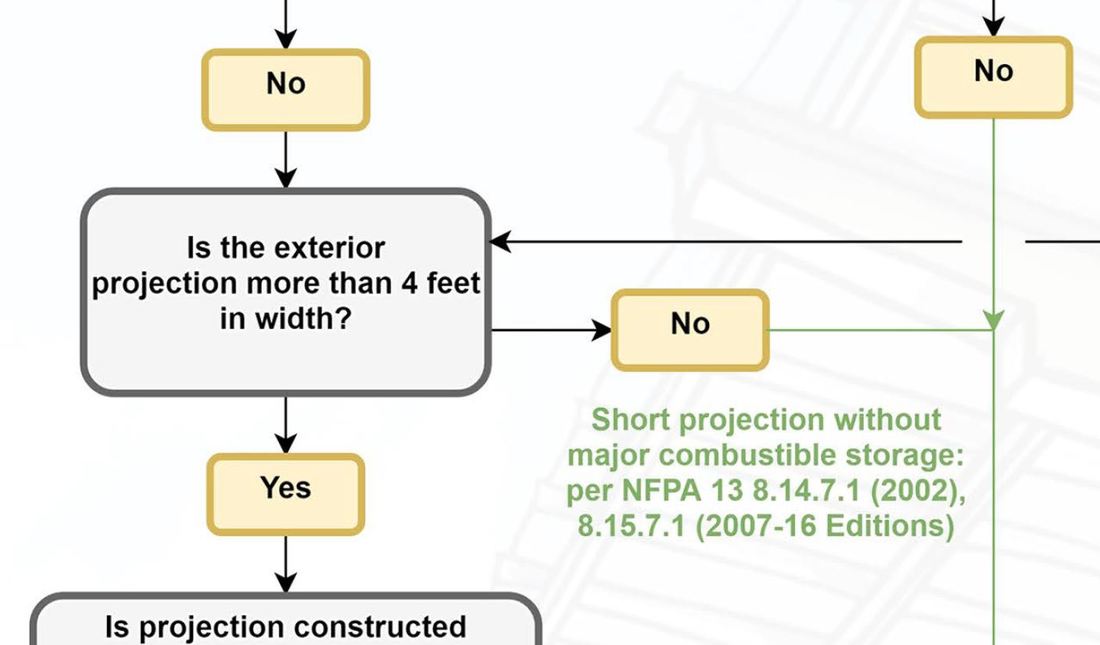
+ No spam
+ Unsubscribe anytime AUTHORJoe Meyer, PE, is a Fire Protection Engineer out of St. Louis, Missouri who writes & develops resources for Fire Protection Professionals. See bio here: About FILTERS
All
ARCHIVES
July 2024
|
 RSS Feed