
|
We've had some breakthroughs with our interactive learning over at MeyerFire University that I wanted to share. If your team could stand to improve their skillset and resources, or you simply haven't looked at our MeyerFire University in awhile, I'd very much encourage you to do so. We are working hard to tangibly shake up the way our industry learns, all for the better. Click the image below to see a sneak preview of what's going live on the University in two weeks (April 29). Thanks for being part of our journey, and I hope you have a great rest of your week! HOW DO WE FIX BAD SPECIFICATIONS?
Last week I touched on a concept of using large language models to instantly review a series of specifications. Thanks for the comments! I’ll write up the step-by-step and incorporate that in a how-to video for posting here and on YouTube. A special shout out to Kimberly Olivas, Brian Gerdwagen and Casey Milhorn on their comments in that thread – very helpful and insightful. The discussion brings me back to two questions I may have inadvertently skipped right over –
A PROBLEM WE CARE TO FIX? If part of a bidding contractor’s value proposition is using their expertise to sort through bad specifications and give an advantage; either in exclusions or clarifications, or change orders later in the process due to inaccuracies, scope not meeting code, or scope gaps. In other words, based on a bidding contractor’s position – there might not be any incentive for them to play their cards for competitors to see through the Pre-Bid RFI process other than a smoother project experience for the owner. A bidding contractor is not a representative of the owner; the consultant is. Ultimately the consultant is responsible for protecting and supporting the owner – which is why they were hired in the first place. Perhaps many contractors don’t look at it that bluntly – but I can understand the sentiment not to tip a hand at project issues when it could mean losing a bid. WHAT’S THE ANSWER? If Pre-Bid RFIs are not the cure-all in today’s pace of estimating – and contractors are not incentivized to be correcting consultant issues – then do we care to actually fix it? For estimators – are bad specifications purely an annoyance for you – or do they cause issues on your projects? Would you prefer that specifications actually be well written? I’m not being facetious – I’d love to know your take on this. ALTERNATIVE APPROACHES If better specifications (and plans) are something we deem better for the industry – and we collectively want better plans and specifications – what is the approach to get there? More specifically, how do we encourage those who don’t really care about fire protection to put a little more effort into their plans and specifications? This was last week’s idea:
Here are some alternative from-the-hip ideas that I’d love to kick around with you and see if you find any of these might be viable: IDEA #1: PUBLISH AN OPEN MICROSOFT WORD FILE BASIC FIRE PROTECTION SPECIFICATION
IDEA #2: CREATE AN AI TOOL FOR CONSULTANTS TO QC THEIR OWN SPECIFICATIONS
IDEA #3: PROMOTE OR CREATE A LOW-COST SPECIFICATION GENERATOR
IDEA #4: HAVE A FORMAL THIRD-PARTY REVIEW PROCESS (A GROUP) FOR SPECIFICATIONS
IDEA #5: PUBLIC HUMILIATION
IDEA #6: YOUR IDEAS
Do you (1) think this is a problem that should be fixed, and (2) what concepts do you think could make a difference? Comment below – would love to foster a deeper discussion on how we might solve this problem before skipping ahead and creating something that might not be impactful. One of the things that frustrates me to no end about our industry are bad specifications. If you want to skip the story and dive right to the end – my ask today is that you comment below on what you would want an automated tool to check for when it reviews a set of specifications? In other words, what issues have you found in specifications in the past that you would want an ideal tool to check for? I’M GUILTY, TOO Before I dive deeper and sound preachy, I have two disclaimers:
WHAT MAKES A BAD SPECIFICATION? What makes a bad fire protection specification? The most dangerous is probably direction which would not meet code minimum. Ambiguity or conflicting information makes bidding difficult. Mandating things which don’t exist for the rest of the industry (such as velocity limitations in hydraulic calculations) can be unnerving and increase cost unnecessarily. Some of the most obvious parts of a bad specification are mandates for products or manufacturers that no longer exist. The goal of a good specification is the same as the plans – clear, unambiguous communication of what is included and not included in a scope of work.  LITTLE RECOURSE
After a project is awarded, a contractor naturally has very little leverage to change the scope of work. Perhaps there are cost-savings options that may be asked of a contractor. Perhaps there’s a change in the project that opens up opportunities to revisit early design decisions. But essentially, after contract award, there’s not a whole lot of leverage against complying with a bad set of specifications. How do we address bad sets of bid documents in our industry? If it’s life threatening and/or egregious, perhaps we could turn people into the governing boards. But how often is that done? How useful is it to permanently burn a bridge for reporting someone that may not even have any consequence? The answer from those I speak with is almost never. Consultants who don’t care about fire protection continue to issue plans and specifications, mostly the same as they always have, with little concern or incentive to change. OUR INITIATIVE Part of creating the community here is recognizing that uplifting everyone makes our industry better. More knowledgeable contractors mean better detailed design and installations. More knowledgeable plan review and inspectors means better policing and better final results across the board. More knowledgeable consultants means that projects flow smoother, owners get what they need, and projects are more timely and on-budget. Part of our responsibility here is to uplift the industry by sharing best practices and making helpful information & tools available that help us all do work better. We have the educational piece (MeyerFire University), we have shorthand tools and cheatsheets. I write posts here. I have ideas in the works on helping improve access to basic, quality sets of specifications. But what about now - as in today? What is the best possible way to actually address a bad set of specifications that will get in the way of a smooth project? PRE-BID RFIs In my opinion, the most underutilized and best way to help foster a smooth project is challenging the scope before bid with a pre-bid RFI. Pre-Bid RFIs (Request for Information) is a documented way to ask questions about the scope of a project before it is bid. These can give an opportunity for a consultant to check their work, check their assumptions, give an opportunity to make a change if necessary, or give a chance to clarify an aspect of the scope. Consultants can choose to play ball – help clarify the job on what should and shouldn’t be included. They can make changes if necessary, and allow bidders to bid apples-to-apples. Contractors can also choose not to play – perhaps double down on the (incorrect) mantra of “this is the contractor’s responsibility to determine”, or something similar. In either case, whether answered or not, Pre-Bid RFIs give the bidders either the information they seek or have greater permission (leverage?) to do as they see fit regarding the scope of the project. SO MORE WORK FOR ME, JOE? Crafting a good pre-bid RFI historically isn’t the easiest thing, though. First – the writer has to digest enough of the project to write something coherent and competent – meaning they need to spend time looking through everything. Second – pre-bid RFIs can sometimes have the presumption that a contractor is causing issues before they’re even on the job. This all comes down to the tone, silly as it might sound. If the pre-bid RFI is accusatory, that’s one thing. But if it’s written to help streamline a smooth project for everyone – then that’s a win for everyone. Third – and perhaps the reason that pre-bid RFIs don’t happen as often as they should, is simply time. Bid days are time crunches. There’s a lot on the line. Going out of your way to clarify a project when you’re already on a time crunch can be tough. This is the piece I’d like to help solve, and I think we can with some of your input. THE CONCEPT What if we had an automated tool that read a set of specifications and generated a helpful, appropriate, Pre-Bid RFI for your project? While you’re reviewing the specifications and putting together your estimate, you do a 3-step copy and paste into ChatGPT (or something similar) that checks a whole host of specification issues and writes a Pre-Bid RFI for you? You could have the time savings (huge), but also have AI do the work for checking for the 30 or 50 or 80 things that have been issues in the past – all stemming from specifications. How convenient would that be? If we could take the onus off of reporting bad players to state boards and instead focused on finding clean, appropriate, and easy ways to help make a project smoother for everyone – without adding any time burden – well that would be nothing short of awesome. What I want to do from here is write a prompt and a step-by-step that I can share back with you all, that incorporates your list of grievances. Essentially – everyone then has access to an easy way to gut-check specifications and get a custom-written Pre-Bid RFI out of it. I need your input though to make it as useful for you as possible: WHAT DO YOU NEED FROM ME JOE? What I would love your input on is your answer to the following: What have you seen in a specification that was clearly wrong which negatively impacted your project? What have you found in a specification that makes bidding difficult, isn’t code compliant, or hurts the project? I’m looking to create a list of checks that AI can do, for you, when it only has access to a project’s specification. Comment below and let me know your thoughts – and in the next few weeks I’ll test and share a prompt and provide instructions back with you on how to use it.
Last week I worked error propagation for a pitot measurement to flow rate conversion.
Because it's a measurement, there is a natural level of precision that we can only estimate that depends on the precision level of each of our measuring points (our tools). Yet, we (maybe just I) often overlooked the concept of measurement error. In this tool (below), I've incorporated the error propagation to suggest a range for the result instead of what we typically express as a near-certain test measurement. So, now, you can convert a pitot pressure into a flow rate and immediately get the error tolerance based on the tools you've used and measurements you've taken. Hardly any additional work. While it may sound trivial, knowing what amount of tolerance we are actually achieving in a test measurement could be the difference between a test pass or test failure - especially in regards to fire pump testing. Check out the tool below, and let me know what you think! It has an IP and SI version built in (I'm finally catching on).
If you're a member of MeyerFire University this will be added to the iOS and Android app automatically.
Thanks and have a great rest of your week! - Joe When you conduct a hydrant flow test, how precise is your resulting measurement? Let’s say a flow test summary shows 82 psi static, 54 psi residual at 956 gpm. Is it really 956 gpm?  Well, no, of course – but 956 is the best resulting estimate of the flow test with the information and measurements we have at hand. It’s where the dial best predicts. But how precise is that measurement, really? Are we certain that it’s 956 gpm and not 957 gpm, or 960 gpm, or 1,000 gpm? Now of course, a hydrant flow test is a point-in-time measurement. It’s not representative of daily fluctuation or seasonal fluctuation. Let’s save that discussion for another time. What I’m really interested in is when we take a flow test or run a pump test, how accurate are our results, really? SIGNIFICANT DIGITS The concept of significant digits is one simple way avoid suggesting a higher level of precision than a measurement justifies. In other words, if our flow test results said 956.21 gpm, we’re suggesting, based on the decimal placement that we actually know that the value is not 956.4 gpm; it’s instead between 956.2 and 956.3. That’s a level of precision that is suggested by significant digits. Technically, if we had a pitot gauge reading of 9 psi during a flow test, then we would have one significant digit. Using one significant digit is very problematic in flow test results. Q=29.84×C×d²×√P In this flow conversion formula above (the Freeman Flow Formula), we take we take pitot pressure (P), opening diameter (d), and the Coefficient of Discharge (C), to get a resulting estimate of flow through an opening. The problem with using the significant concept is that a pitot reading of a single digit value would mean that we round our resulting flow would yield one significant digit. LOW PITOT MEASUREMENT NFPA 291 actually recommends that pitot readings less than 10 psi should be avoided, if possible. That would mean flowing fewer outlets to get a higher pitot reading to avoid inaccurate readings. So, at least in theory, three 2.5” outlets with a C-factor of 0.90 and a pitot of 9 psi each would result in a flow estimate of 1,511 gpm being rounded to – what – 1,000 gpm or 2,000 gpm? The concept of ‘significant digits’ here would result in massive rounding error. This line of logic is where I was really curious about our flow test results – or really any measurement of flow, such as pump testing. How precise are our measurements? BIG GAUGES, SMALL TICKMARKS If you’ve tried to take a close reading and nitpick the difference between 96 and 97 psi on a 300 psi gauge – that can be extremely difficult to do. Yet, at least in the case of fire pump testing, that result can be the difference between passing or failing a fire pump test. 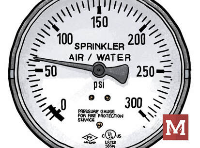 How precise can we read a higher-range gauge with small or grouped tickmarks and a small-diameter face? If you don’t think that’s a high-stakes proposition, then I’d invite you to wrap up final acceptance testing on a federal project with every stakeholder present and watching. It can be high stakes. Perhaps the more appropriate way to understand precision is by doing error propagation on this conversion. Error propagation is a sore point for me, as I pretty much failed every physics lab in college that required it. Time to shed those demons. If you’re not into math, skip ahead to the summary to see where I ended up. I want to show my work here as I haven’t seen this done and I’m very much for transparency and getting feedback, especially when I venture a little beyond my own fenceposts. ERROR PROPAGATION FOR FLOW TEST CONVERSION Error propagation is a fancy way to describe the reliability of the resulting calculation. How precise is the result? That’s what we want to know – and knowing so can help us make more informed decisions in our assessments.  A formula with multiple variables, where each have their own uncertainty, the overall uncertainty depends upon how each variable affects the final result. In other words – if I’m not exactly sure about the numbers I’m putting in, how unsure should I be about the answer I get out? IMPACT OF DIAMETER VS. PITOT PRESSURE In this equation, a percentage error in measurement of a diameter could have an outsized effect on the resulting flow since diameter is squared. To run an error propagation on a formula involving variables which are multiplied together, we square the relative uncertainty (change in a measurement divided by the measurement), square them, add them together, and square out the result.  EXAMPLE: 60 PSI GAUGE So, let’s say we ran a flow test where we were certain in the Coefficient of Discharge (0.90), we measured and were confident in the diameter of 2.5 inches (within a 1/16th of an inch), and took a pitot reading of two side outlets each at 8 psi using a 60 psi gauge with 1% accuracy. Practically speaking, that’s a very reasonable amount of tolerance of a normal hydrant flow test or fire pump test. With those results, we would calculate a total flow estimate of about 950 gpm.  How precise is that flow? 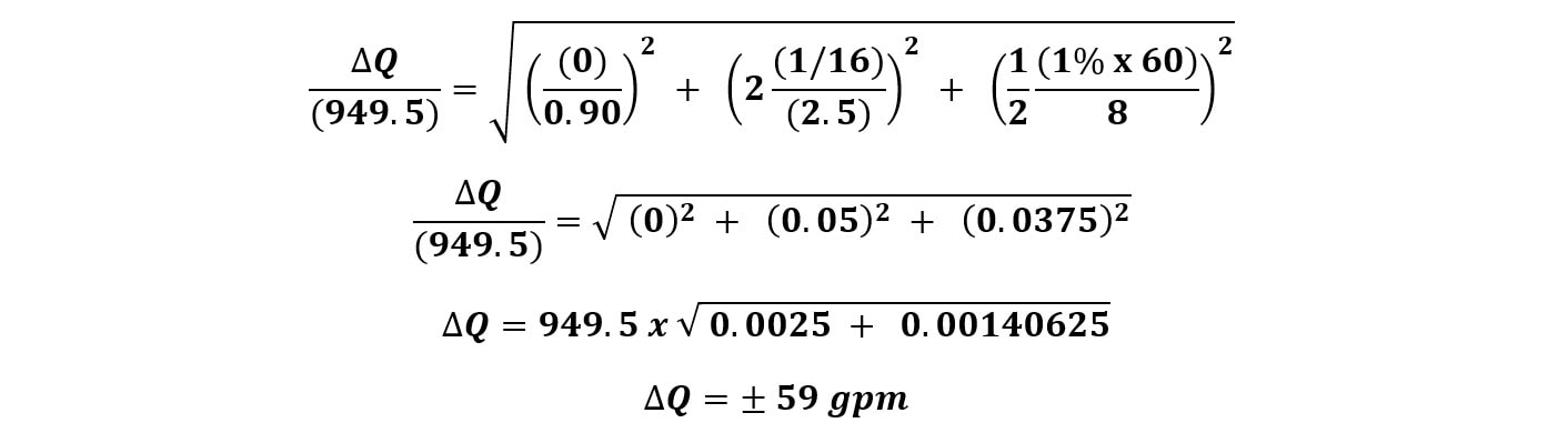 (Error in flow test reading measuring opening within 1/16” and pitot with 60 psi gauge) So, with a variation of + 59 gpm, our resulting flow estimate would be 950 gpm + 59 gpm, or a resulting range of between 890 gpm and 1010 gpm. That’s a pretty wide variation – and it’s certainly a lot wider than I would have expected considering we’re using a 60 psi gauge with 1% accuracy. EXAMPLE: 100 PSI GAUGE What would happen if we used a 100 psi gauge with 1% accuracy?  (Error in flow test reading measuring opening within 1/16” and pitot with 100 psi gauge) EXAMPLE: 300 PSI GAUGE Taken to an extreme – what if we used a 300 psi gauge to measure pitot? A bad idea for sure (it’s nearly impossible to read sensitive low amounts, and likely in the least-accurate portion of the gauge. But just for kicks:  (Error in flow test reading measuring opening within 1/16” and pitot with 300 psi gauge - which we would never recommend doing) EXAMPLE: 60 PSI GAUGE WITH IMPRECISE DIAMETER Now, what if we were less confident in the actual inside diameter of the hydrant side outlet? What if we thought it was 2.5”, but only within an 1/8th of an inch? With our 60 psi gauge:  (Error in flow test reading measuring opening within 1/8” and pitot with 60 psi gauge) Yikes! Did you notice that? Even with a 60 psi gauge, if we only know the inside diameter within an 1/8th of an inch, it’s worse than using a 100 psi gauge. Knowing the precise inside diameter is important as it has a huge effect on the level of precision. HOW DO WE IMPROVE PRECISION? Based on the inputs – there are a few key ways to improve the precision of flow test readings when we use pitot gauges to estimate the amount of flow. I’m interested in writing more on this in the coming weeks, but there are a number of ways in which we can improve the precision of our flow testing and have more confidence in our results. #1 MEASURE THE OPENING SIZE First – and probably the most important based on our calculation – is to know the exact diameter of the orifice opening. If we are flowing out the side of an outlet, we actually need to measure, with precision, the inside diameter of that opening. As I’ve been told, not all inside diameters are equal. They depend on the exact make and model of a hydrant. I’ve made this mistake before and assumed all 2.5” side outlets are the same inside diameter. To improve precision, take a careful measurement of the exact inside diameter of the opening down to the 1/16th of an inch. Alternatively, using a factory-created attachment with a factory-milled opening will help define and make that variation go away. A known diameter with a very tight factory tolerance helps us reduce or eliminate this concern altogether. #2 USE SMALLER RANGE GAUGES In general, we want to use the smallest range for the gauge possible. Using a 300 psi gauge to measure anything within 0-30 psi is problematic. Not only is that a less-accurate range for a gauge (near the ends), it’s extremely difficult to read. The tickmarks just become too small to read well. Instead, we want to use the lowest gauge range that’s possible for the test. If we’re expecting results below 100 psi, can we use a 100 psi gauge instead of 200 or 300? If we’re measuring pitot and expecting values under 60, can we use a 60 psi gauge? Even a 30 psi gauge? The bigger the tickmarks and the smaller the range, the better we’re going to be able to see and read the results.  Using a lower-range scale gauge can lead to far-easier reading of the gauge, but also be within a more accurate range for the gauge itself. #3 LARGER-DIAMETER GAUGES
This goes against my “travel with small things” concept, but larger-diameter gauge faces are so much easier to read in the field. They cost more. They’re bigger. But man are they easier to pull values from. Again – on an important fire pump closeout with many people all watching – having nice clear results to prove the system works as it should helps. #4 USE CALIBRATED GAUGES For fire pump testing, NFPA 20 requires that all gauges undergo annual calibration testing and be accurate within 1 percent. (NFPA 20-2022 Section 14.2.6.1.2) For fire hydrant flow tests, that same mandate doesn’t necessarily apply. NFPA 291 is a recommended practice, and requires calibration within 12 months, but is not necessarily enforceable in the same way that NFPA 20 is. Now, if you’re on a federal project and NFPA 291’s “shoulds” become “shalls”, then there are enforceable teeth. But for private practice work, many flow tests are simply run with whatever gauge is on the truck that day. Using a calibrated gauge will obviously hone in for more precise measurement. #5 USE STREAM-STRAIGHTENERS NFPA 291 now specifically states a preference for playpipes or stream straighteners to improve the accuracy of readings. Not only do these address the precise opening sizes we talked about earlier, but they hold the pitot measurements in a fixed-in-place mounting position. This also means we should be measuring at exactly the right center-of-stream location. This is explicitly listed now in NFPA 291 (2022) Section 4.6.2. SUMMARY Doing a little error propagation highlights a few things about the measurement process in a calculated way. We can look at the accuracy of our input measurements an in turn, get a level of confidence about the resulting range of flow from those measurements. The more precise we are able to measure, the more confidence we have in the result – which is both an obvious ‘gut-feeling’ but can also be mathematically proven. YOUR TAKE I’m interested in your take. What are your tips for more accurate readings? What stories do you have about fire pump acceptance testing or hydrant flow tests in this regard? NEXT STEPS I’d like to venture down this rabbit hole just a little further. My next thought is to apply the error propagation concept into a quick calculator tool where you could see your error range yourself – and experiment with different situations. You might just find an error range based on your normal test equipment that could present your test results in a more appropriate and transparent way. That's TBD (to be developed). Thanks for reading – and, as always, for fighting the good fight. Have a great rest of your week. - Joe
On the MeyerFire University side of things we've been getting into the fundamentals of hydraulic calculations and the basis for how we perform calculations today.
One of the concepts that I had not explored in any kind of detail was the Hazen-Williams formula itself - outside of perhaps a few hand calculations here or there when studying for a NICET or the PE Exam. It was developed early 20th center by Gardner Williams and Allen Hazen when they studied records of friction loss measurements from a range of experimenters. The formula they derived was empirical. For hydraulic calculations - it's been the staple our industry and the basis behind our systems today. 
I'd be particularly interested in diving a little deeper than we typically would to get a job done, and that might come in posts here in the next few weeks. How do we reduce pressure loss in our systems? What does the actual construction of the formula tell us about flow in our system? WHAT THE FORMULA SUGGESTS The exponents here are relevant - because of that 1.85 exponent - if we double our flow, then our pressure loss increases by 260%. If we triple our flow, then the pressure loss is 7.6 times the original! Exponents affect the C-Factor too. If our C-Factor improves from 100 to 120, our pressure loss drops 29%. What applications could that have for us? Well, if we install nitrogen on a new dry system - our C-Factor goes from 100 to 120. That could be a big deal on the right projects. What about diameter? With the 4.87 exponent, that has the biggest effect of all. If our diameter doubles, our pressure loss drops 97%! Even going from 2-inch to 2.5-inch drops pressure loss by about 60%! Of the variables in the Hazen-Williams equation, diameter has the greatest impact on friction loss. HYDRAULIC PARALYSIS We know that intuitively as pipe diameter is our first go-to for solving hydraulic issues and is also the one element we have the most control over as a designer. One concept not to gloss over, though, is the pipe schedule. Even seemingly minor differences in pipe schedule (thickness) can have a major effect on pressure loss considering that the effects of diameter have an exponential effect on pressure loss. If you're banging your head against a wall trying to round out a hydraulic calculation, make sure that all of your pipe diameters are optimized (of course), but also check that your pipe schedule is accurate. The difference between a Schedule 40 and Schedule 10 calculation over a long enough distance and a sensitive-enough portion of the calculation could have a big effect on pressure loss. Also - if you're ever stuck - try our tipsheet on ways to get out of a jam (Article #1 and Cheatsheet #2). In experimenting around with different values, I went ahead and put together a small calculator that does a Hazen Williams calculation with a few helpful lookup tables already included. If you don't see the tool below, click to check it out:
If you're well into your career, this might not present a whole lot of practical need - any sprinkler hydraulic calculation program already has this incorporated of course.
What I wanted to do is simply break out the calculation to explore the effects in a little more detail. Take the sample calculation, and tweak the inputs just a bit - you can do so by clicking on a dropdown, making any selection, then use the up/down arrows on your keyboard to flip through values quickly. YOUR TAKE What do you see that people often miss about the Hazen Williams formula? What, if anything, would you want to see on this tool as a means of learning about the fundamentals? I think it would be a little interesting to start a dialogue on the limits of Hazen Williams and potential range of accuracy (that is, actually explore it mathematically and possibly disprove some of the frustrating assumptions that tend to pop up regularly). What do you want to see? Water velocity? Limits? Comparison to Darcy-Weisbach? Let me know below. Hope to nerd out a little and see what we can come up with together. A couple weeks ago we updated the NFPA 13 shop drawing checklist with new references to the 2019 and 2022 Editions of NFPA 13. With the 2022 update, the NFPA 13 Committee revamped the list of requirements for “working drawings” in the 2022 Edition. It was pretty much gutted and rewritten. DOES A 2022 UPDATE CHANGE ANYTHING? What impact does this actually have for me or my team? Who uses the 2022 Edition right now? Well, perhaps no local jurisdictions have adopted the 2022 Edition yet. Perhaps that’s a few years away still. But what about US Federal work, which references the latest standard edition at the time of the job posting? Or large corporate or healthcare users who might mandate adherence to the latest codes & standards? Or, what if we’re just being prudent and looking to be ready to adapt when it is enforced? Well, yes then, it could have an impact on your process whether you’re creating the working drawings or reviewing them. Here’s the list of noteworthy changes to the working drawing list as I understand them. Please note that I’m far from a Committee member and it’s only my interpretation of the list. As this plays out in time, I’m sure plenty of gray areas will get sorted out in online discussions, informal clarifications, or code changes. 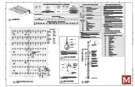 The list of shop drawing requirements went through an entire revamp with the 2022 Edition. #1 SHOW THE MEANS OF FORWARD FLOW (ADDED IN 2019) A means of conducting a forward-flow test has long been required, but historically overlooked or was possibly achievable by flowing out of a fire department connection or main drain (for very low hazards). We talked about the big change for a fixed means of forward flow that was introduced in 2019 and clarified in 2022. How does this affect shop drawings? Well, we now need to locate and identify the means of forward flow on the plans [NFPA 13-2019 Section 27.1.3(25) and 2022 Section 28.1.3(18)]. 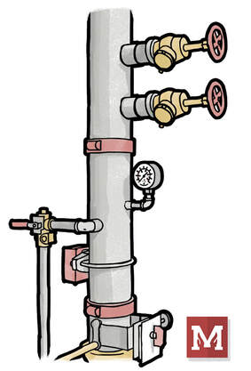 The location and labeling of the means of forward flow is required in the 2019 and 2022 Editions of NFPA 13. #2 THE BUILDING CROSS-SECTION WAS REMOVED If you’ve ever prepared or seen a random building cross-section on shop drawings (with no pipe or sprinklers shown), that’s because NFPA 13 had a requirement showing a full-height cross section that showed ceiling construction, protection for non-metallic pipe, and structural member information. This was a constant source of review comments, which does help clarify what’s going on, but is only a single slice of a building that otherwise could be very complex. In the 2022 Edition, the list goes away from the building cross section and instead requires identification and locations of major structural members [2022 28.1.3(11)], labels of Obstructed or Unobstructed where applicable [2022 28.1.3(11)], and ceiling heights labeled on the plans [2016 23.1.3(45), 2019 27.1.3(5), and 2022 28.1.3(9)]. From a matter of design and practicality, showing ceiling heights and structural members on the plans themselves helps us all communicate a bit better. Showing all the ceiling heights, structure, and Obstructed vs. Unobstructed with plan labels was something I incorporated a few years ago and helped me be more disciplined during design. It also beats out a single-slice section of a building that may or may not actually clarify how much of the building is being constructed.  A building section that doesn't detail sprinklers or pipe, nor is at a position or scale that effectively communicates the relationship of structure, ceilings, and coverage - doesn't do a lot of good. It may not have been the original intent of NFPA 13 anyway. The NFPA 13-2022 Edition removed the requirement for a whole-building cross section but added plenty of labels and requirements to the floor plans to adequately address the original reason for inclusion. #3 LIGHTS, DIFFUSERS, AND OTHER CEILING FIXTURES Many bid specifications require that lights, diffusers and other ceiling-mounted devices (fire alarm, occupancy sensors, etc) be shown on sprinkler working drawings. Doing so certainly helps prove that the ceilings have been coordinated – or at least other systems considered. But now that’s been codified. In the 2022 Edition, Section 28.1.3(8) requires diffusers, lights, and other ceiling fixtures or major MEP equipment just above or below the ceiling be shown on the sprinkler working plans. This seems easy enough to require for a consultant – but for a sprinkler contractor, pulling in this information can be a chore – especially if the sprinkler subcontractor doesn’t get a full set of CAD plans to begin with. Hopefully, with this being codified, a sprinkler contractor’s request for CAD backgrounds on this information gets a little easier to push back up the food chain. 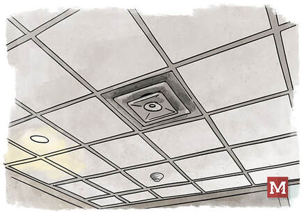 We know lights, diffusers, and other ceiling fixtures will be on a project. Now we're required to have them on sprinkler installation plans. #4 PLACARD INFORMATION Hydraulic Data Nameplate information has long been required to be shown on the working drawings, but now the hose demand, method of calculation, and total flow and pressure have been added to the list. This comes from the 2022 Edition, 28.1.3(23c). #5 OWNER’S CERTIFICATE INFORMATION NFPA 13 has long required that a signed Owner’s Certificate to be submitted with working drawings (1999 8-1.1.2, 2022 14.1.4, 2007-10 22.1.4, 2013-16 Section 23.1.4, 2019 Section 27.1.1.1(4), 2022 Section 28.1.4). Now, with the 2022 Edition, required information from the owner’s certificate is required to be shown on the plans [2022 28.1.3(14)]. This includes storage materials, storage heights, water supply information, and whether seismic bracing is required. This is discussed in more detail in 2022 Edition Section 4.2.  The Owner's Information Certificate has been a requirement to be included with working drawings, but now the required information from it is also required to be shown on plans, starting with the 2022 Edition. #6 DESIGN CRITERIA FOR EACH SPACE The 2022 Edition clarifies that design criteria for each room or space be shown on the plans, including hazard classification everywhere, and commodity classification, storage type, configuration, height, and packaging for storage areas [2022 Section 28.1.3(15)]. That’s often critical yet hard-to-find information for plan review. This clarification puts some teeth to requiring that information be shown on plans. #7 FLEXIBLE DROP INFORMATION The 2022 Edition introduces requirements to indicate corresponding k-factor, length, manufacturer, maximum number of bends, minimum bend radius, and model for flexible drops when they’re used [2022 Section 28.1.3(17b)]. While many designers already indicated at least some of this, having the maximum number of bends and minimum bend radius on the plans could go a long way in helping on-site inspection make sure that the install actually adheres to the design intent. Not a terrible idea. #8 MORE SEISMIC DETAIL The 2022 Edition requires more detail on several seismic bracing components. These include design angle categories, flexible coupling locations, locations of seismic components, maximum spacing, penetration clearances, and zones of influence all to be shown on the plans [2022 Edition Section 28.1.3(22)]. IMPACT FOR PLAN REVIEWERS The “working drawing” revamp in the 2022 Edition shakes up an area of the code that hasn’t changed much in some time. For plan reviewers, this is a welcome relief. Many of the updates and additions are simply requiring pockets of information that a plan reviewer needs to know for proper review, but is really difficult to surmise if they’re outside of the design development process. Having teeth to require that commodities and storage arrangements and Obstructed & Unobstructed be identified on the plan will go a long way in checking due diligence has been done in key areas. IMPACT TO DESIGNERS For designers? This could be a tall ask. There’s some major adjustment here. For designers who traditionally have been very thorough in plan preparation and documenting each step of the process, this will be more of a matter of simply sharing some of that documentation. For designers that may not have gone into this level of depth – there’s certainly going to need to be more time dedicated to the process. More time to ask the owner for input. More time to ask for more complete backgrounds for coordination. More time to document, label, and identify details on plans. It’ll take more time. If designers already feel crunched by design time budgets, then it’ll be be an adjustment for everyone. IMPACT TO ESTIMATORS For estimators? When the 2022 Edition (or later) gets enforced, plan on designers needing some additional time to take this on. Time adds for design will be greatest for buildings with storage, seismic projects, or jurisdictions who provide thorough review. There’s plenty of teeth to the the updated list, so it’s less of a “well these things are technically supposed to be provided in the spec” and instead “NFPA 13 requires this to be shown.” Less room to maneuver, in other words. TAKEAWAYS Personally, I like these changes. They allow for clearer communication of intent, which is the point of drawings in the first place. It’ll allow designers to be more thorough in their process. While that might sound contradictory (why would a designer want to be pushed to be more thorough?), many good designers lament that the pace and expectation for flying through design is too fast. Having NFPA 13 be the backbone of what needs to be submitted gives designers a tangible justification to do a more thorough (better) job. The NFPA 13 requirements can play the part of the villian, not the designer who’s trying to do things at a depth that they feel is needed. Hope you enjoyed the recap here, and that you have a great rest of your week. Keep up the good work. - Joe Last week we updated the NFPA 13 shop drawing checklist with references to NFPA 13 2019 and 2022 Editions. While code updates like this are traditionally modest, the NFPA 13 Committee revamped the entire list of requirements for “working drawings” in the 2022 Edition. It was gutted. We’ll expand on that more next week. This week I’d like to key in on one very impactful change that I think will affect many of us in how we design systems going forward. FORWARD-FLOW REQUIREMENT HISTORY A forward-flow test has long been required in NFPA 25 (dating back to at least 2002). The purpose of the test is to verify that a backflow preventer is capable of fully-opening in a fire – or at least to the extent that it allows enough water to flow to satisfy the sprinkler system’s demand. A means of conducting a forward-flow test has long been required, but not necessarily readily implemented. For many lower-hazard systems, it was a test that was possible by flowing out of a fire department connection or main drain. WHY NOT FLOW OUT THE FDC? White it was possible to do a forward flow through an FDC, this approach was never practical. I can’t stand on a high horse here – it was the approach I long used from a design perspective. It’s not practical because conducting a forward-flow test out of an FDC would typically require a system to be shut off, drained, check valve reversed, put back into service, tested, shut off, drained, check valve put back into place, and put back into service. And that was if the clappers on the FDC were removed or restrained in a way to allow enough water to pass through. It’s a tall ask. USE THE MAIN DRAIN? Flowing out the main drain could be a solution for forward flow, but practically speaking how much water can flow through a 2-inch main drain, especially if there’s an OH1 or OH2 demand? Do we have a way to verify how much water we’re flowing, so that we know the test passed? Some have used our own calculator to estimate the amount of water flowing through a main drain by using this orifice flow calculator - https://www.meyerfire.com/blog/a-new-fire-sprinkler-test-drain-flow-calculator That calculation is based on pressure flowing through an opening – either an orifice or pipe diameter – and doesn’t incorporate the losses that occur through the length of a main drain or the fittings along the way. It’s going to be too generous on the amount of flow coming through a main drain – which is good if we’re wanting to know how much water a plumbing drain needs to accept – but bad if we’re trying to prove forward flow based on it. I would suspect that a supply-side calculation (where the available pressure dictates the flow) through a fully-open main drain would be the best way to predict hydraulically how much flow a main drain could flow. If that’s well above the system demand (including hose allowance), then a main drain could be the means to flow. But a 2-inch main drain is very likely not an answer for forward flow for most systems. I’ll leave that discussion open – perhaps there’s a tool we could construct to account for main drain losses and perform that supply-side calculation. PERMANENT MEANS FOR FORWARD-FLOW Somewhat fortunately for those of us who like black and white guidance (myself included) –the NFPA 13 committee closed up the gray area in the 2019 Edition by requiring that an arrangement for conducting the forward flow test, at the minimum flow rate of the system demand (including hose allowance), would be provided “without requiring the owner to modify the system to perform the test.” This comes from NFPA 13-2019 Section 16.14.5.1.1. In the 2022 Edition, the committee went further.  A fixed means of forward flow, like hose valves on a test header or system riser, will become far more commonplace once the 2019 and 2022 Editions of NFPA 13 are adopted and enforced. A 2-1/2” HOSE CONNECTION FOR EVERY 250 GPM A test connection is now required for forward flow tests, where now a 2-1/2” hose valve is required for every 250 gpm (950 L/min) of system demand. This total flow must include the hose allowance where applicable. Generally, if there are interior hose valves, then this would need to get added in. So - an Ordinary Hazard Group I system that may have a demand of 270 gpm (with 250 gpm outside hose allowance), would still need two 2-1/2” hose valves for the forward flow test fixed in place downstream of the backflow preventer. For larger systems, or those with interior hose connections? We could be looking at three or more hose connections just for forward flow. This comes from NFPA 13-2022 Section 16.14.5.1.1. That’s a noteworthy change. For a code-minimum, sprinkler-system-only type of project, that’s a tangibly different cost and look to a part of the system. Does this have to be a test header on the outside of the building? Not necessarily, though that would be nice for future testing. Could the hose valves be on a riser in a room that has exterior access? Depending on the room and goals for the building – that could be reasonable. There are two provisional sections that allow existing hose connections to be used for the test (16.14.5.1.2), and other means to test are allowed “as long as the system doesn’t require modification to perform the test and is sized to meet the system demand.” The later comes from NFPA 13-2022 16.14.5.1.3.  Is a fixed test-header on the exterior of the building required? No, but it could be convenient for future testing in areas where theft is less of a concern. HAVING TEETH
But in general – we don’t have a “use the FDC” workaround any longer. For those in IT&M, we finally have a sticking point to give an ability to do this test without tinkering with the system. For those in design, we finally have a magic section of code that we can show to justify providing a means of the forward flow test. For those in review and inspection, we have the teeth to enforce it. Hopefully, in the long-run, having systems tested for forward flow will identify backflow preventers aren’t functioning and we no longer have them in buildings ready to fail when a fire happens. Hopefully, this pushes buildings to a bit safer and helps us a be a little more confident in the system’s ability to fight a fire. SHOW ON WORKING DRAWINGS While the means is an installation question – NFPA 13-2022 Section 28.1.3(18) requires that working drawings locate and identify the means of forward flow. It’s no longer a “how do you plan to do this test?” type of comment and will soon be “show the location and label the means of forward flow, per 28.1.3(18).” MY FORWARD-FLOW STORY Are we really just testing the backflow preventer here? Well, yes. In part. But actually flowing an entire system demand tells us quite a bit. It means that our water supply is capable of flowing the full system demand, and all the pipe in-between the water supply and the backflow is also open-enough to flow the full system demand. I once had a project where a tap was made to the city supply main. It was a live tap or “hot tap,” where a drill punctured the side of the city main and a new 6” street valve was installed and our 6” underground came in and fed the building. It was a brand-new 3-story building that was going to have overnight guests. The tap wasn’t fully-made. In fact, as we found out later through a lot of cost and trouble, only a ¾” pilot drill bit made it through the city main. It wasn’t all the way drilled-in. Instead of a 6” tap, we had a ¾” tap. Static pressure to the building was fine. We could run a main drain test just fine (the residual dropped, but the main drain isn’t flowing all that much). Remember – the initial main drain test sets the threshold to check against in the future. We could flow the inspector’s test just fine. When we conducted the forward flow test and opened a couple 2-1/2” hoses – we had no water. No pressure at all. It wasn’t until we conducted the Forward Flow test that we knew there was a problem. Where it not for the Forward Flow test, we would have had a brand-new building, which, by all other measures we would have thought was designed and installed properly – all protected by a system with water that was squeezed through a ¾” hole. While the backstory of testing the Forward Flow may be more about the backflow preventer, the test does give us confidence in the supply up through the backflow preventer being able to handle the system demand. If we measure the flow coming from the forward flow, and also stick calibrated gauges on the upstream cock and downstream cock of the backflow – we can know a whole lot about the health of our system that day. What’s the static pressure? What’s the loss through the backflow? What’s the base of riser pressure at the system demand? How does that compare to our design? We can get a lot of information just from this one test. END SOAPBOX That’s my soapbox rant for today. As with all we write and do on this site, I hope you’ve found it helpful. Keep fighting the good fight, and have a great rest of your week. - Joe Have you had a project with an overhang that needed sprinkler protection and extended just beyond the throw of a dry sidewall sprinkler? It’s a smooth, flat or nearly-flat overhang that’s, say, 21’-6” wide, and in an environment that will dip below 40 degrees F at some point. What are your options then? OPTIONS All of the extended coverage dry sprinklers we know on the market cap out at 20’-0” horizontal throw. That would have been our best option. We could look at using a dry system. There’s the additional cost of the valve, slope requirements, a hit on the remote area size, more corrosion potential – and on and on. It’s costly. We could look at an anti-freeze system. Those come with more restrictions than they used to, but at a minimum would involve an RPZ and now pre-mixed antifreeze solution. Additional cost. Heat trace the pipe? That’s problematic, at best. It needs to function 100% of the time that it’s needed, or pipe will freeze. It needs to be supervised. It needs to be maintained. And when in conjunction with pipe insulation it looks terrible. In short, an overhang that’s just beyond the reach of a dry sidewall sprinkler can take us to a whole new cost tier in the design of a sprinkler system. CODE-COMPLIANT CREATIVITY We had just this situation on a project a few weeks ago, and tried to think creatively to get a code-compliant solution that’s best for the owner, yet doesn’t spike the cost for a dry sprinkler system that only serves four sprinklers. Now normally, sprinkler design tends to be a one way street. An architect designs a building. It gets bid and handed down to the sprinkler contractor. The sprinkler contractor “makes it work” with what they’ve been given. If a consultant is on-board, this would be a great opportunity to pick off challenges like this and advice the architect and owner on ways to mitigate this cost spike for a small project. Perhaps the overhang is designed at 19’-6” instead of 21’-6”. Perhaps they build it with all non-combustible materials if it otherwise didn’t have storage below. Those could be helpful changes that reduce the overall cost in a major way, but may not be a major detriment to the owner’s goals for the building. #1 SHORTEN THE OVERHANG Regardless, we suggested that the width of the overhang be actually shortened to allow a sidewall’s throw to cover the distance and prevent the need for a whole dry system. That didn’t go anywhere. #2 EXTEND THE REACH OF A DRY SIDEWALL We then asked if a soffit could be built to allow a sidewall it’s spacing of no more than 20’-0”. The soffit wouldn’t have to be heated. It could simply be framed (hopefully of non-combustible studs) with sheetrock or a “Hardie Board” or some other skin. It could be almost completely empty on the inside. The goal would be to give a dry sidewall sprinkler a back to collect heat and be installed properly. KEY RULES There’s a few notable rules that come into play here, though.
So working backwards, a soffit that is say, 2’-0” wide and 2’-0” tall would allow a dry sidewall sprinkler to:
But then, we need coverage below the soffit too, right? This could be accomplished with a flexible dry pendent, such as the V3517 dry flexible pendent sprinkler. Just like the dry sidewall, the flexible dry pendent could contain water back on the warm interior space.  DIGGING DEEPER We also would want to offset these locations on plan, so a pendent isn’t immediately under a dry sidewall. Offsetting the locations in plan could help potential cold-soldering concerns. We’d also want to be sure that both the dry sidewall and the dry flex pendent would be able to be replaced at some point in the near future. NFPA 25 used to require sample testing or replacement every 10 years starting at 10 years after installation, but the 2020 edition bumped that starting point up to 15 years and the 2023 Edition bumped it again to 20 years after installation (NFPA 25 2017-20 Section 5.3.1.1.1.6, 2023 Section 5.3.1.1.1.5). To accommodate replacement and testing, we might need a way to get access to the inside and the soffit in the future (access panels or future cutout). COST & CONSEQUENCE After all this effort – will the soffit cost more? Sure. Would it cost as much as a dry or anti-freeze system? No, it shouldn’t. Does it help with corrosion and IT&M in the future, considering we wouldn’t have a dry valve and an additional nitrogen system or air compressor? Yes, that’d help too. Just an idea that might help address those “in-between” situations that could spike cost for a smaller-sized project that otherwise wouldn’t need it. What are your thoughts? Have you tried this before? What tips would you suggest? Hope you’ve found this interesting and perhaps moderately helpful, and I hope you have a great rest of your week! Until I did some research recently, I hadn’t realized that NFPA 72 breaks out different definitions for Unwanted Alarms by fire alarm systems. In a way, as an FPE I always kind of shuttered and turned a blind eye to the reality of how much of the rest of the world views fire alarm systems – as a nuisance. Imagine yourself flipping through a book that you’ve pulled off the shelf at the library. It’s quiet; the librarian shushers are about and keeping the noise down. Then suddenly the fire alarm system activates – it’s loud, startling, What is the first thing that comes to mind when this happens? As a fire person, I jump into detective investigator mode. I understand what kind of inputs would trigger an alarm, so I’m naturally very curious on what might have happened. But what about the ‘Average Joe?’ If it’s a calm library on a quiet afternoon, are they in a rush to leave? Or is their first thought “it’s probably a false alarm?” I can tell you by experience that unless there is another signal, like the smell of smoke, sight of smoke, or others moving quickly – most will pay attention and mostly ignore the alarm. They assume it’s a false alarm until they have evidence that suggests otherwise. FALSE ALARMS DON'T REFLECT WELL This is really bad for our industry. The prevalence of false (unwanted) alarms makes people apathetic to the alarm in the first place, and it reflects poorly on us. Is the reduction of false alarms more important than detecting an actual fire event? Of course not. We need these systems to detect and alert us that something is up. But as a downstream effect or a lesser-priority, we also should pay attention to finding ways to reduce unwanted alarms. We want our systems to be trusted and we want people to react when they someday do activate. WE JUST TALKING IT&M? Much can be said about regular inspection, testing, and maintenance of the system. Old and dirty smoke detectors can certainly cause alarm when there isn’t a hazardous condition. But from the very beginning, we can help prevent unwanted alarms by design. That’s something that designers, engineers, plan reviewers and inspectors can help prevent from the very beginning. BRAINSTORMING IDEAS I don’t have all the answers here, but I would like to start the dialogue and open discussion on clever ideas that help reduce unwanted alarm. NFPA 72 has a list of terms that fall under Unwanted Alarm, which is any alarm that is not the result of a potentially hazardous condition. It lists Malicious Alarm (person acting will ill-intent), Nuisance Alarm (alarm by a non-hazardous condition), Unintentional Alarm (person triggers but by accident), and Unknown (no known cause). My gut says that Malicious and Nuisance are the most preventable. How can we discourage someone from activating an alarm as a prank (Malicious), and how can we reduce Nuisance Alarms where there is no actual threat? Here is my shortlist – I am very interested in your tips and takes on additional ideas to avoid Unwanted Alarms by design. #1 REMOVE MANUAL PULL STATIONS (WHERE ALLOWED) The most-accessible method for an occupant to activate a fire alarm system is with a manual pull station. The IBC (most commonly-adopted model code in the US) has exceptions to remove manual pull stations for fully-sprinklered buildings. When this exception is offered, it’s worth considering. Many new construction projects require fully-sprinklered buildings anyways, so eliminating the exposure for a pull station in a highly populated area would reduce the potential for pranks. That being said, always consider the alternative. Are we talking about a middle or high school situation, or a hospital? Is it a dormitory, which is all-but-guaranteed to have a 2am alarm activation during Finals week? Or is it a critical care facility where there are multiple patients who cannot self evacuate? Manual Pull Stations do have their purpose and place in the industry; so we still want to consider the context and purpose for them. One important note that’s often missed – using the exception to remove manual pull stations doesn’t remove all of them in a building. One pull station must still be installed “at an approved location,” just not at all exits. #2 USE DUAL-ACTION PULL STATIONS If we can’t, or don’t want, to eliminate manual pull stations at all exits – then let’s think about securing them. Can we make the pull stations a little more involved to activate? Would going from a single-action (just pull down) to dual-action (push in and pull down) help prevent accidental activations? It’s possible, though I personally haven’t seen data to suggest it. I can’t imagine a teenager being discouraged by a minor additional action if they already plan to activate a system. But could it prevent a tall and curious five year old from activating the system? Possibly. Going from single-action to dual-action isn’t a notable cost difference, so this would be fairly easy to execute. If you have data on this – be sure to chime in in the comments. #3 PIEZO COVER FOR MANUAL PULL STATIONS Now “Prank” isn’t a formal term here, or at least not yet. But many of my personal experiences with false alarms was during college in the dormitories. How can we make activating a pull station troublesome for someone who is actively looking to empty a 1,000-person dormitory as a “prank”? One way is to put covers with a piezo alarm on the pull station itself. The piezo buzzes as soon as the cover is lifted, which draws attention to the location. If someone is activating the system during an actual fire, the logic is that they shouldn’t be deterred by a buzzer. But someone who’s trying to “get away” with something? Maybe the attention is a deterrent.  Can using a Lift Cover with local Piezo alarm discourage malicious alarms? #4 VIDEO MONITOR PULL STATIONS AT EXITS Perhaps a better long-term solution isn’t a buzzer but a security camera at the location. If exits are already being monitored for security in that area, why not get a camera placed to include the pull station? If it’s much harder to avoid discipline, perhaps the security camera acts as a deterrent. While this might sound expensive – just imagine how many malicious alarms happen in some occupancies? The cost, time and effort of fire departments responding to calls that should have never been placed in the first place? It’s extremely disruptive and very well could lead to fines too. Addressing some of this upfront, when the building is being designed or renovated, could have lasting financial benefit to the owner. #5 SIGNAGE AT MANUAL PULL STATIONS Along the line of logic for security cameras – what about the threat of security cameras? Even just basic and clear signage right above the pull station of “SMILE, YOU’RE ON CAMERA” would be an inexpensive but potentially effective way of deterring bad players. Having a reminder for consequences may just be as effective even if a camera is not actively recording. If you’re a graduate student and looking for a research paper – maybe test this out and let us know. #6 SMOKE DETECTOR LOCATION Thus far we’ve focused on manual pull stations, and that’s because they’re the most easily-recognized way for anyone to activate the system. But what about the nuisance alarm? Perhaps the most front-of-mind false alarm is burned popcorn activating a nearby smoke alarm. Why is that smoke alarm there in the first place?  Can locating required floor-level smoke alarms further away from cooking appliances help prevent nuisance alarms? Well, typically in homes, smoke alarms are required within sleeping areas, just outside of sleeping areas, and on each floor level. Similar requirements are found for residential occupancies. The IBC is explicit in the areas that need smoke detectors or smoke alarms in Section 907.2.
If a smoke detector is required in the area, how can we improve the situation? Can we shift the location to be as far-away from cooking sources as possible, but still be along the path of egress that we’re seeking to satisfy the IBC and NFPA 72? Many times it seems that during design, the smoke detector is just a hex with an “S” on it. It’s just a symbol that gets popped wherever there’s blank space on the CAD plan (I’m guilty of this). We need to be better than that. If a smoke alarm or smoke detector is anywhere near cooking appliances (stoves, microwaves, ovens) – then let’s get those detectors further away but still meet code. That extra distance means that normal cooking exhaust is going to diffuse and be less likely to trigger the smoke alarm. Here again – think about context, what we’re monitoring, and what we’re trying to achieve with the detection in the area. #7 USE THE UL 268 7TH EDITION One of my favorite improvements concerning smoke detection is that the UL 268 Standard for Smoke Detectors for Fire Alarm Systems, recently added a specific test, informally called the “Hamburger Test,” that requires a smoke detector or smoke alarm to not activate under specific cooking conditions. On a side note, the 7th Edition also includes a test for correctly responding to burning foam, which better matches modern furniture padding material. These additional requirements have come into play with the 7th Edition, which is now mandated for newly manufactured smoke alarm and smoke detectors. This is a huge step in the right direction to trigger less nuisance alarms. If we have the opportunity to install or specify UL 268 7th Edition detectors, that might be a major value-add for the owner. I don’t know the current status of availability or whether the manufacturers have caught up to the requirement yet, but the 7th Edition of the standard is currently mandated for new devices. YOUR EXPERIENCE What tips do you have? What are some practical considerations you make when designing or reviewing fire alarm systems? If you’re an AHJ, consider kindly advising owners or designers to consider these things by passing along the “lessons learned” can have a tremendous value to the owner. They can say no where it’s not code-required, but having been in the consulting space I’m incredibly appreciative of tips to consider that is in the interest of the owner. Comment below with your tips or ideas that you like. As always, thanks for being part of the community here! |

ALL-ACCESS
SUBSCRIBEGet Free Articles via Email:
+ Get calculators, tools, resources and articles
+ Get our PDF Flowchart for Canopy & Overhang Requirements instantly 
+ No spam
+ Unsubscribe anytime AUTHORJoe Meyer, PE, is a Fire Protection Engineer out of St. Louis, Missouri who writes & develops resources for Fire Protection Professionals. See bio here: About FILTERS
All
ARCHIVES
July 2024
|
 RSS Feed